Jekyll2024-06-14T12:03:12+00:00https://ruby-on-wheels.github.io/feed.xmlRuby on WheelsA developer on the road.Completing the bathroom2023-01-04T00:00:00+00:002023-01-04T00:00:00+00:00https://ruby-on-wheels.github.io/blog/completing-the-bathroomWith the basic furniture units like the wardrobe, seating area, and kitchenette completed, I could focus on finishing the bathroom, which I had started constructing in spring.
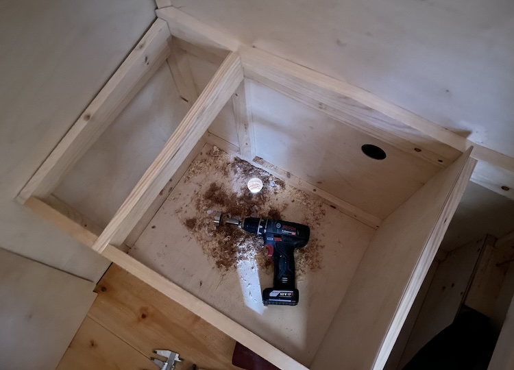
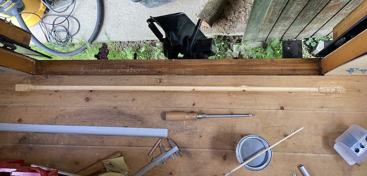
To begin with, I drilled two holes in the floor. One for the urine drain in the toilet box, making it easy to empty the urine tank from the outside.
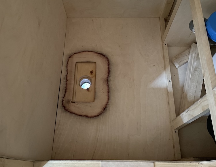
And another one for the drain in the shower.
Building the toilet
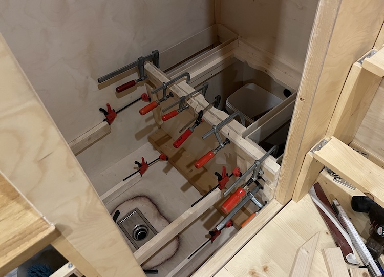
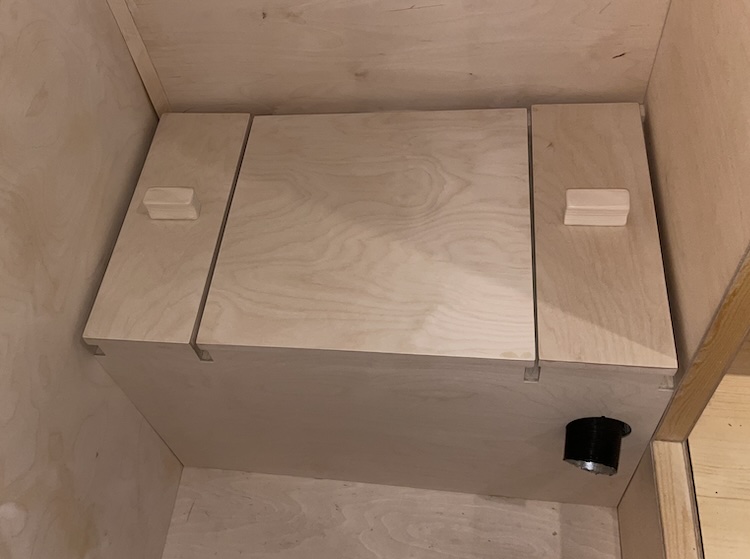
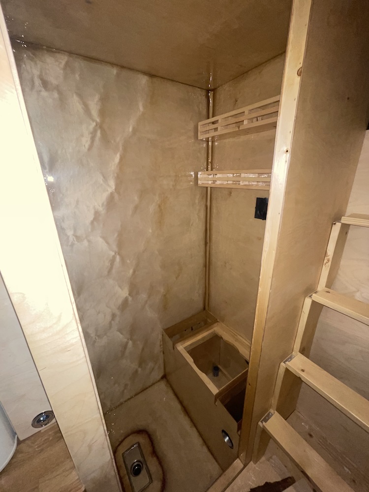
To make the most of the available space, I added walls around the toilet box, creating extra storage room for toilet paper, cleaning supplies, and similar items.
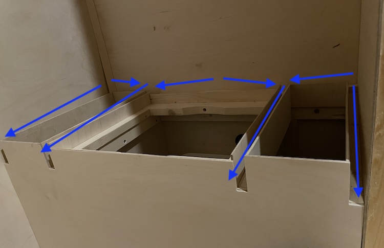
Around the toilet box and storage compartments, I constructed forward-sloping channels to ensure efficient water drainage while showering.
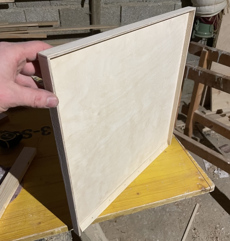
Side overlapping edges on the lids of the storage compartments were designed to prevent water from entering.
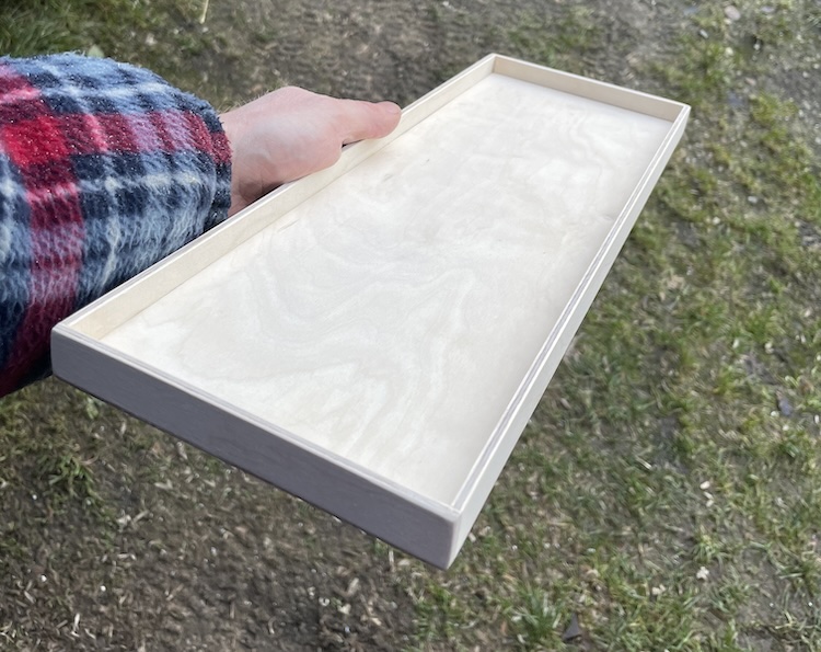
I applied the same technique to the toilet lid to ensure the toilet would stay dry during showering.
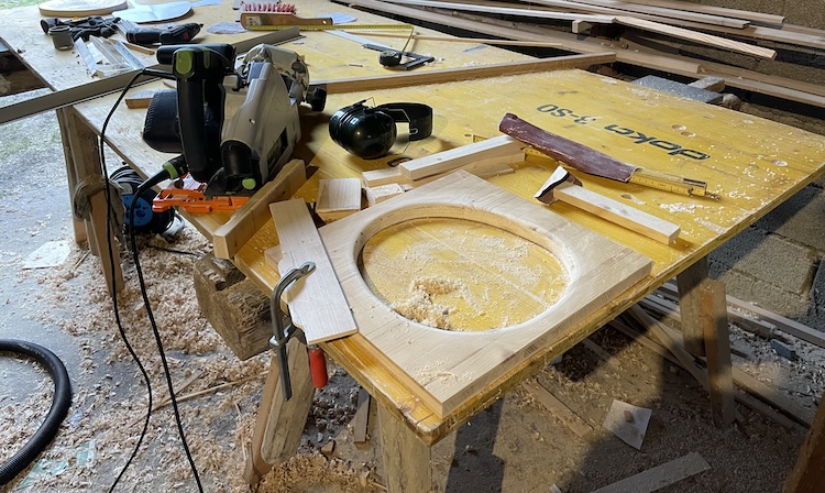
After finishing all the lids, I built a comfortable toilet seat.
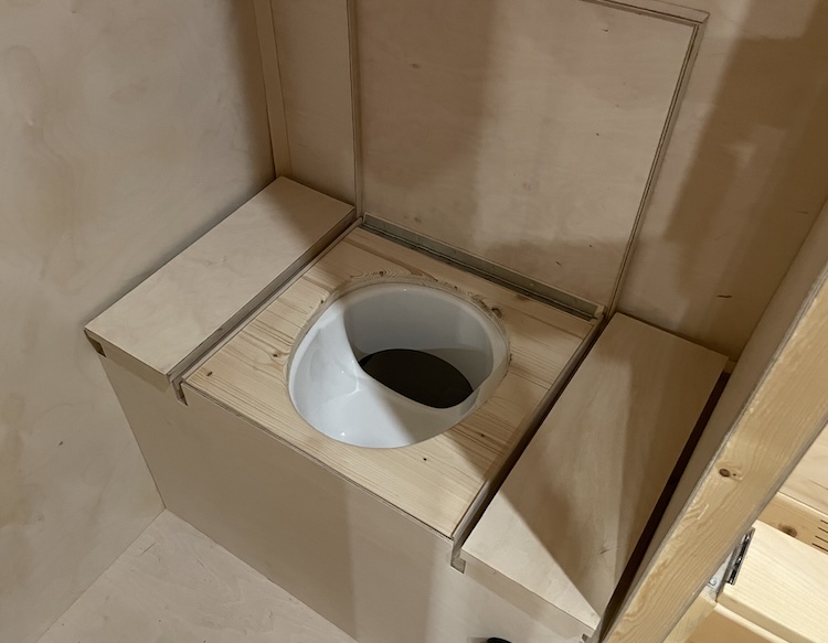
Under the toilet seat, I installed the same toilet separation kit that I had used for the toilet in my previous van.
Additional handles on the lids would make opening the storage compartments easier.
Building a shelf
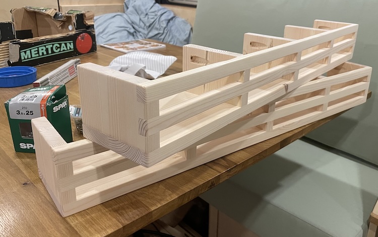
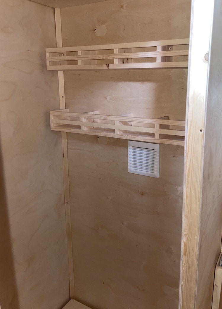
In my previous van’s shower, there was no storage space for bathroom items. Seeking more comfort in the new setup, I built two shelves out of pine wood.
Mounted on the back wall of the bathroom, the shelves provided ample storage space.
Building the door
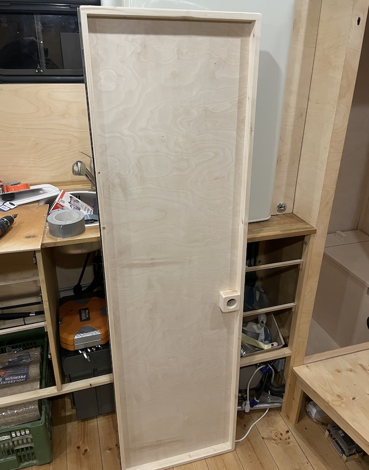
For the bathroom door, I utilized the cutout from the outer wall to preserve a consistent wood grain pattern, ensuring a cohesive appearance. Since the 4mm birch plywood was very thin, I constructed a reinforced frame using pine wood.
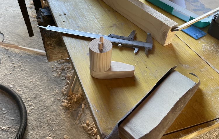
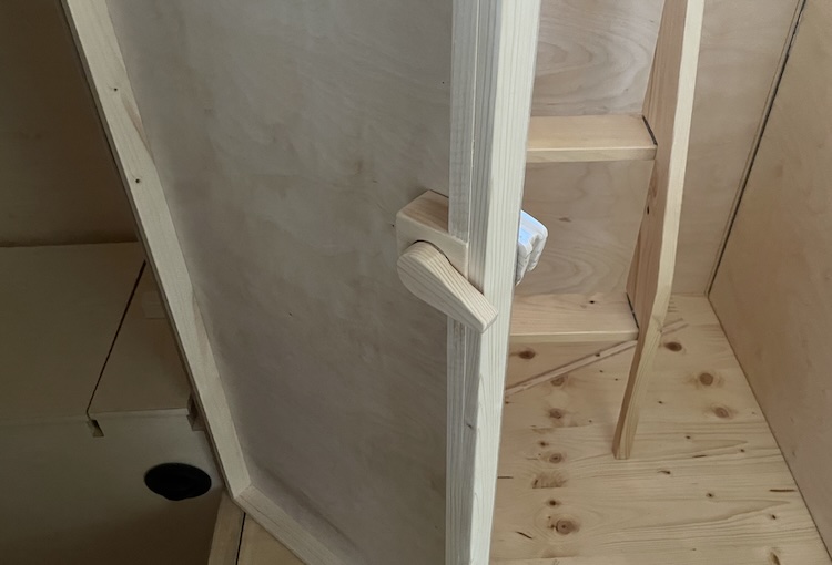
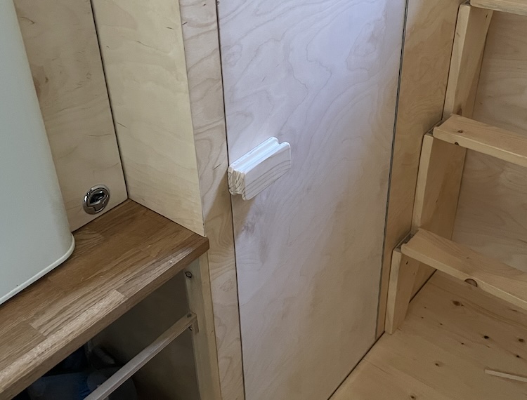
I crafted a simple rotating latch,
which enabled locking the door from both inside,
and outside.
Laminating the shower
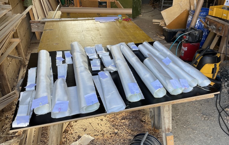
After completing all the wooden parts, I cut fiberglass mats for each piece, the walls, floor, and ceiling.
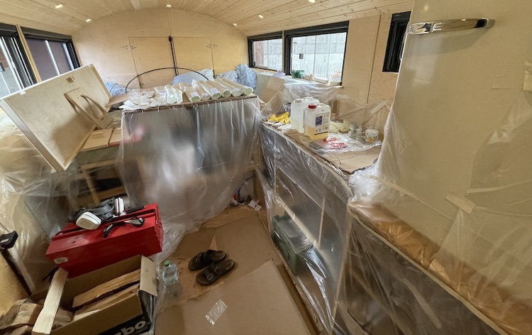
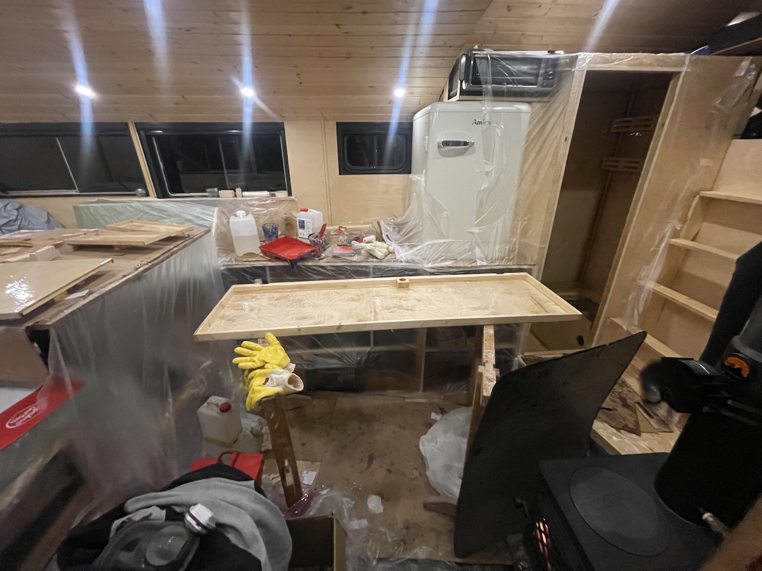
Prior the major laminating process, I prepared the cabin and carefully taped everything off.
While the wood stove ensured an ideal processing temperature, I began laminating the loose parts.
And then proceeded to laminate the entire bathroom cabin.
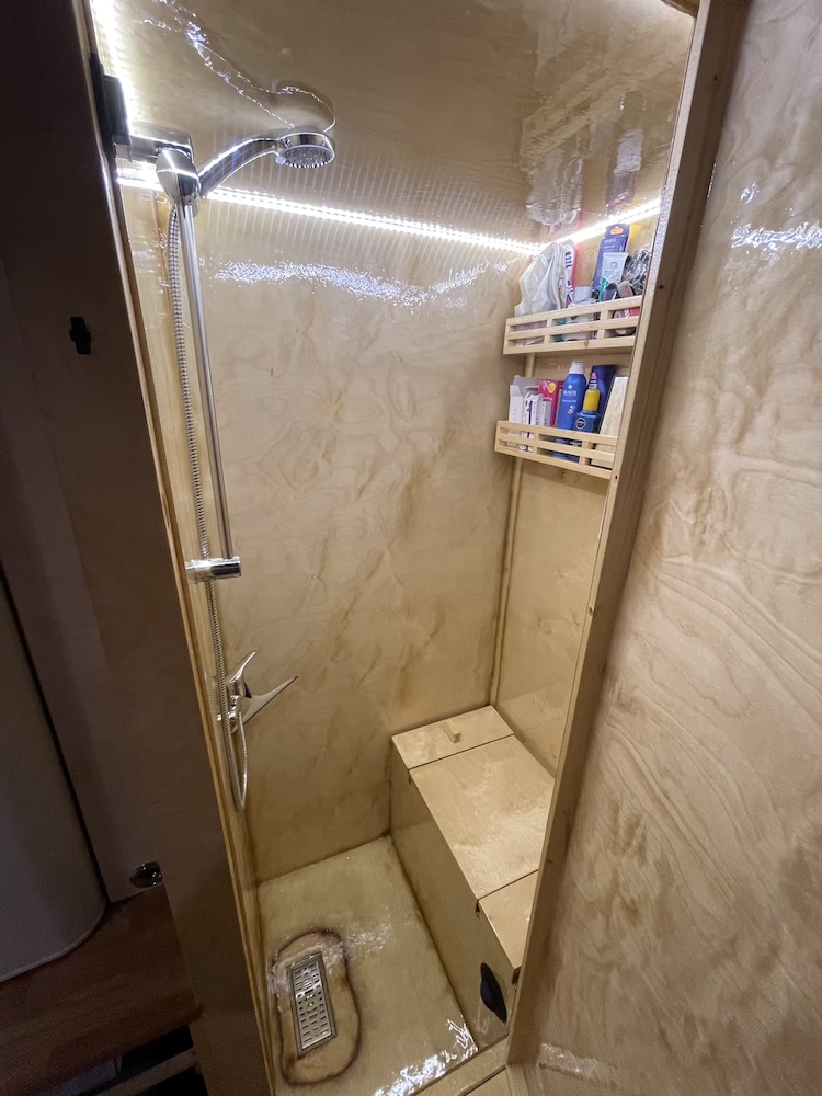
After the epoxy resin had cured, I wired the LED lighting and installed the shower fixture. The bathroom was finally ready for use!
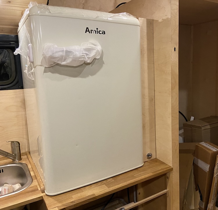
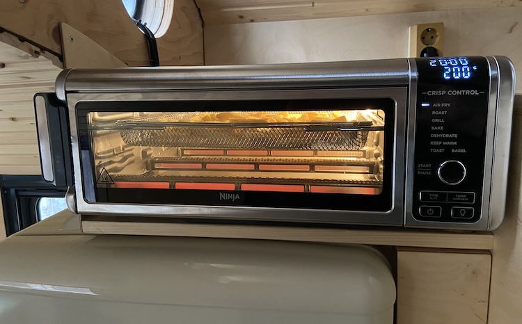
]]>Building the kitchenette2022-12-02T00:00:00+00:002022-12-02T00:00:00+00:00https://ruby-on-wheels.github.io/blog/building-the-kitchenetteI envisioned a larger kitchenette for my truck compared to what I had built in my previous van. While I was quite satisfied with the sink and the extendable faucet, I aimed for two cooking burners instead of just one, readily available without any modifications. Instead of a cooler box, I wanted to experiment with a regular domestic refrigerator featuring a freezer compartment. Additionally, I was considering a multi-functional oven serving as an air fryer, grill, oven, toaster, and dehydrator. This setup was intended to ensure that the kitchen in my truck would be on par with a standard household kitchen, leaving nothing to be desired.
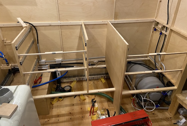
The roughly two-meter-wide space between the seating area and the bathroom cabin seemed to provide sufficient room for the kitchen. To begin, I initiated the construction of the side walls for the lower cabinets.
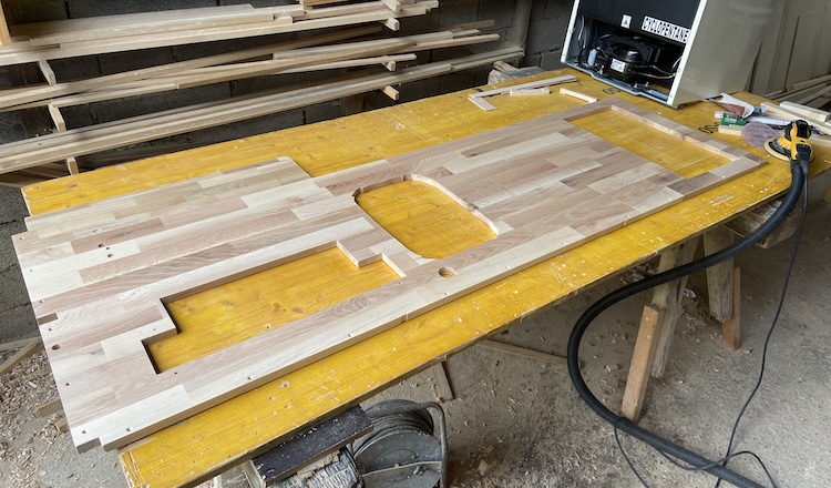
Subsequently, I cut the countertop to size and sawed out the recesses for the kitchen appliances.
After sanding and oiling, the customized oak board was ready for installation.
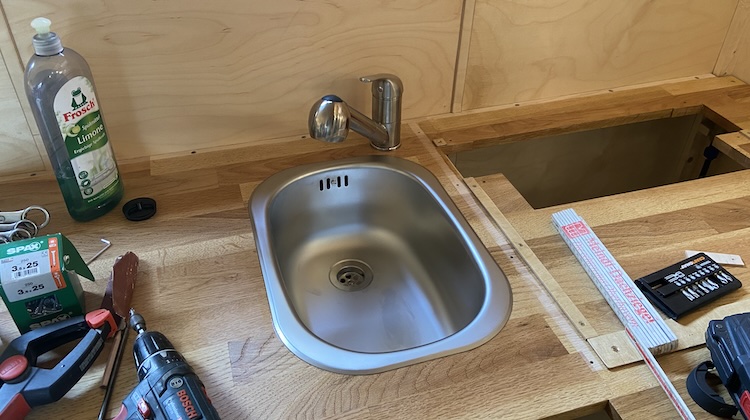
The extendable faucet was easy to install.
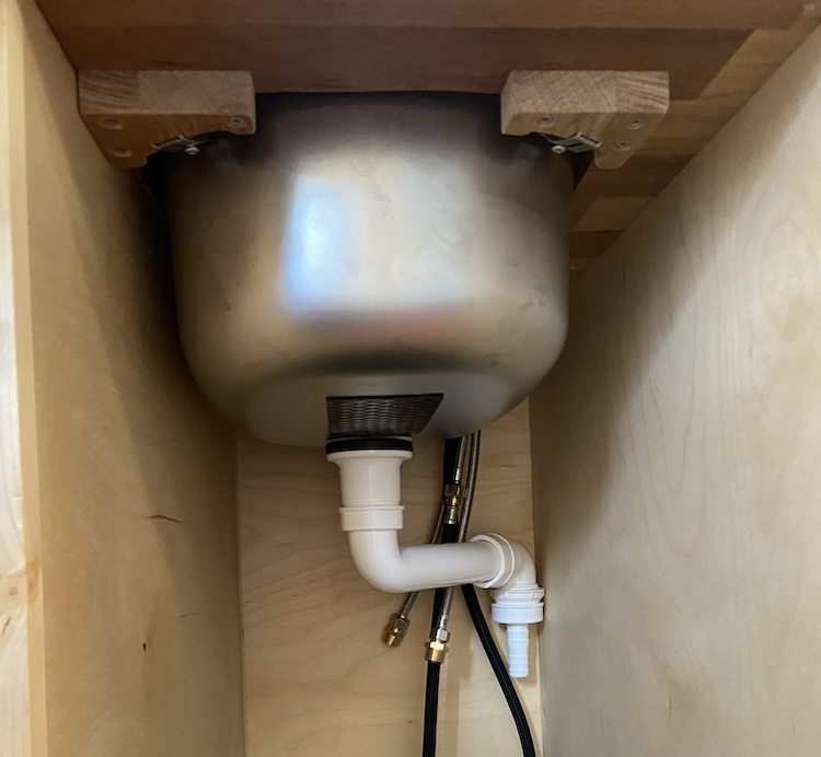
After sealing the sink with silicone on the countertop, I secured it from underneath using custom-made wooden adapters.
I ran a few cables into the side wall of the bathroom cabin,
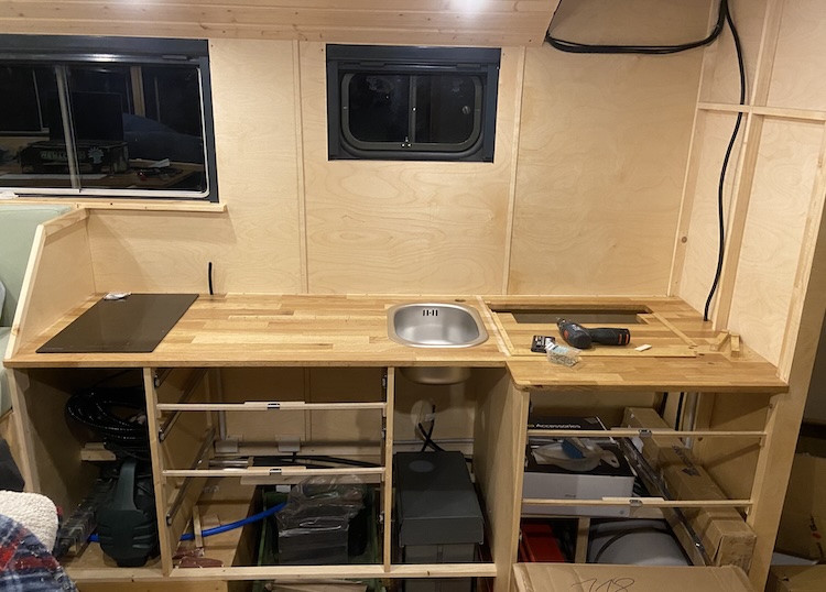
and finally, I installed the outer paneling.
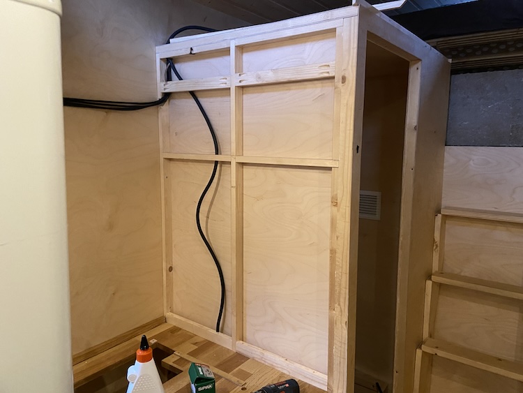
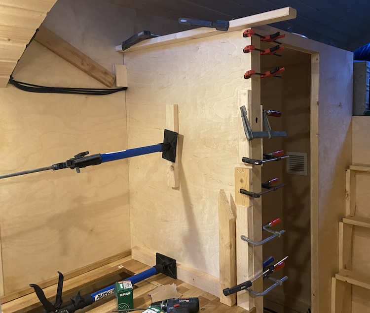
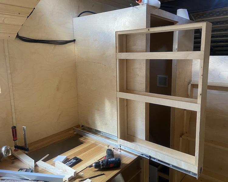
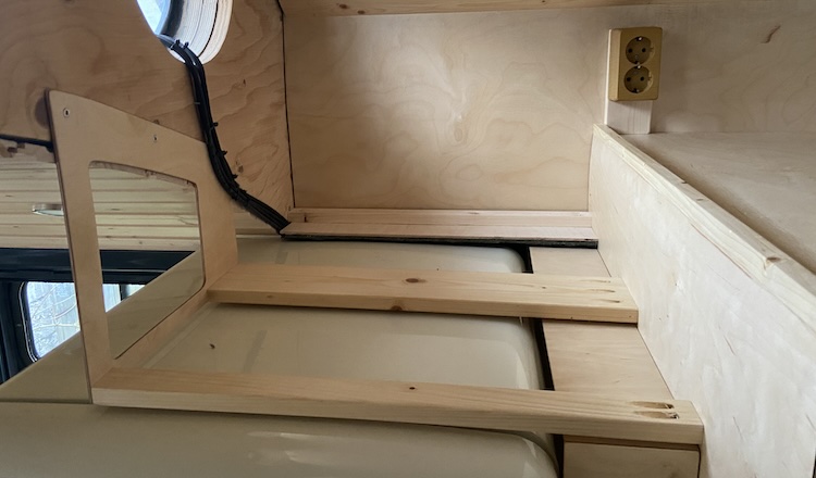
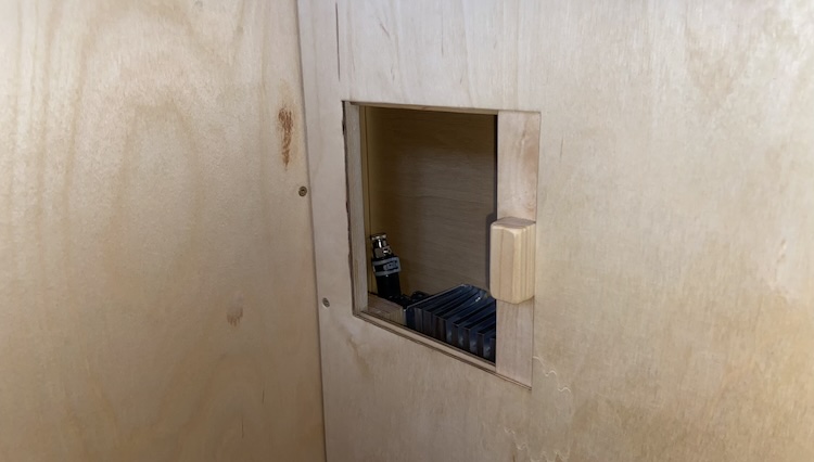
The refrigerator had to be positioned with some lateral distance from the bathroom cabin to allow the door to be properly opened without hitting the slightly protruding side wall of the bathroom. Since I didn’t want to leave the approximately 10cm-wide gap between the refrigerator and the bathroom unused, I built a vertical pull-out cabinet with three compartments.
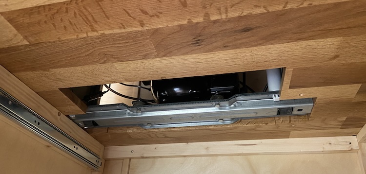
I removed the front feet of the refrigerator to allow the rear rail with the compressor unit to be recessed into the kitchen countertop.
Placing the refrigerator into the millimeter-precise cutout and utilizing the threads originally intended for the front feet, I securely fastened the refrigerator, preventing it from moving during transit.
After securing the refrigerator in its designated spot, I proceeded building the bracket for the oven.
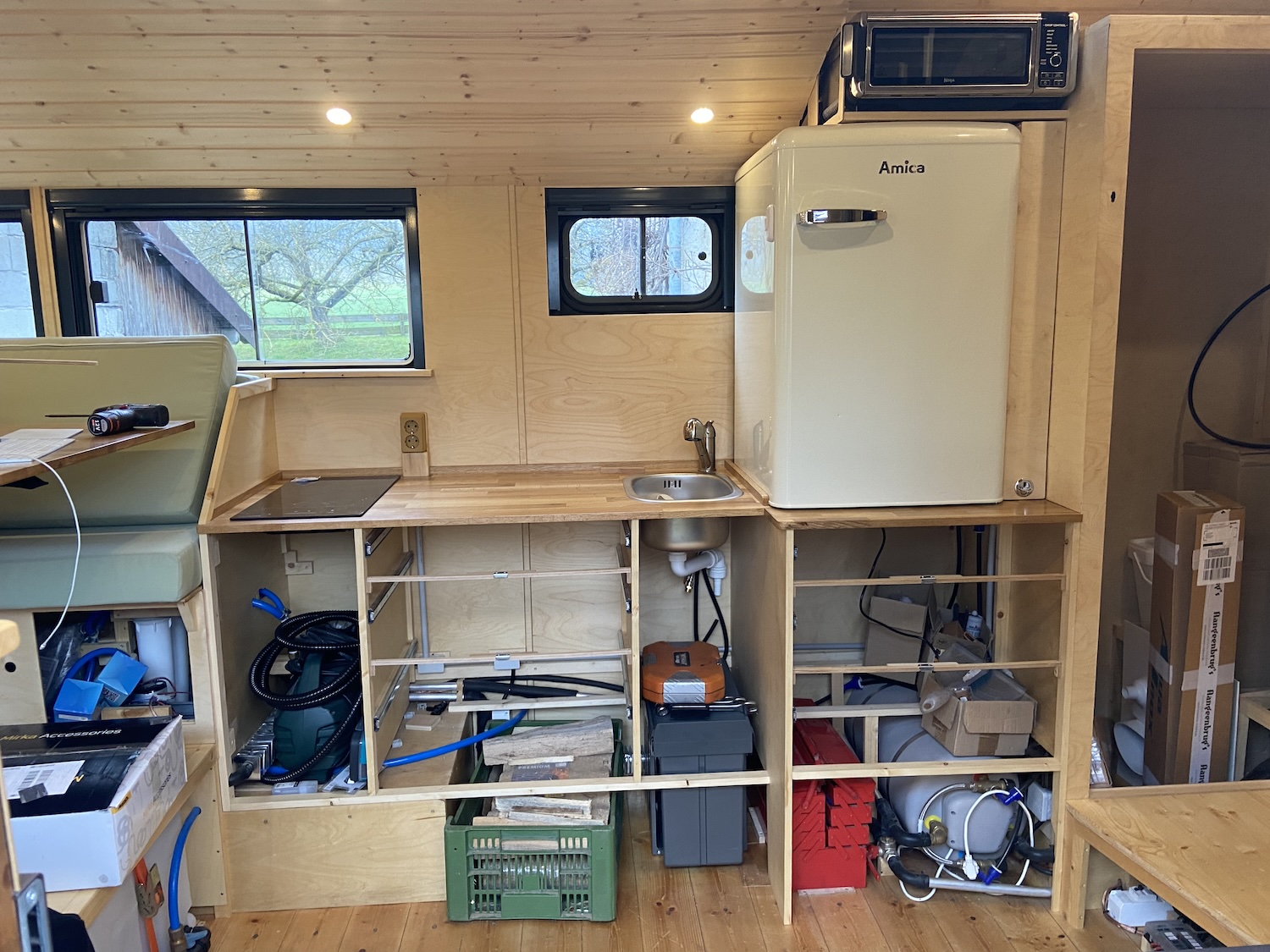
Et voilà, the fundamental units of the kitchen were ready for use: an induction stove, a sink, a refrigerator, and a multi-function oven.
The initial batch of homemade fries from the air fryer tasted especially good! :wink:
The improvisational built pull-out cabinet proved to be an incredibly useful storage space—no wasted space! :+1:
From that point onward, I could finally enjoy cooking in my new home.
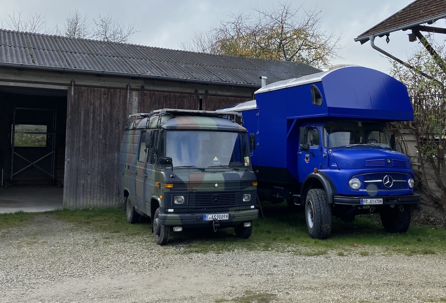
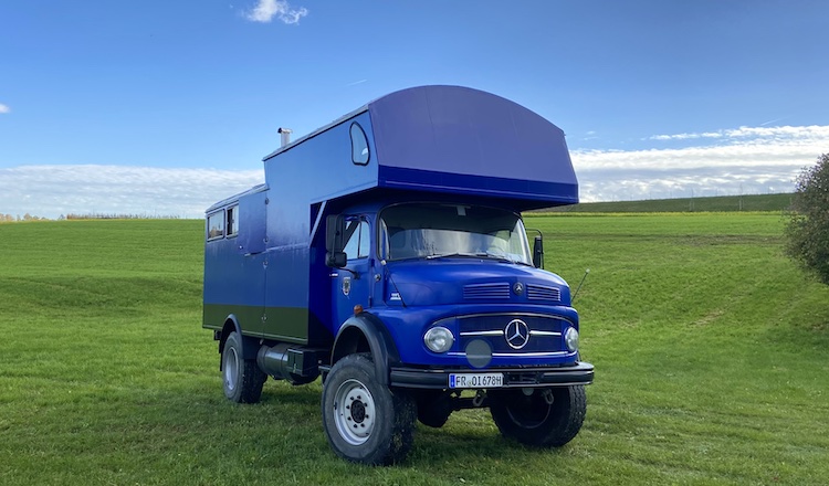
]]>Selling my Mercedes 508D2022-11-09T00:00:00+00:002022-11-09T00:00:00+00:00https://ruby-on-wheels.github.io/blog/selling-my-mercedes-508dAn era had come to an end: After over 4 years of incrediblyamazingexperiences with my self-converted Mercedes 508D, I decided to say goodbye to my dream camper van. Upon buying the Mercedes 1113 truck, I understood that eventually parting ways with one of my vehicles was inevitable. Owning two vintage vehicles simultaneously felt out of place for a nomad like myself.
Maintaining the good condition of these old, beautiful, and reliable vehicles would require regular maintenance and care. While the truck’s conversion had reached an advanced stage, I spent hardly any time in the 508D. Yet, I had to take care of the vehicle repeatedly, which distracted me from working on the truck and gradually became more of a burden.
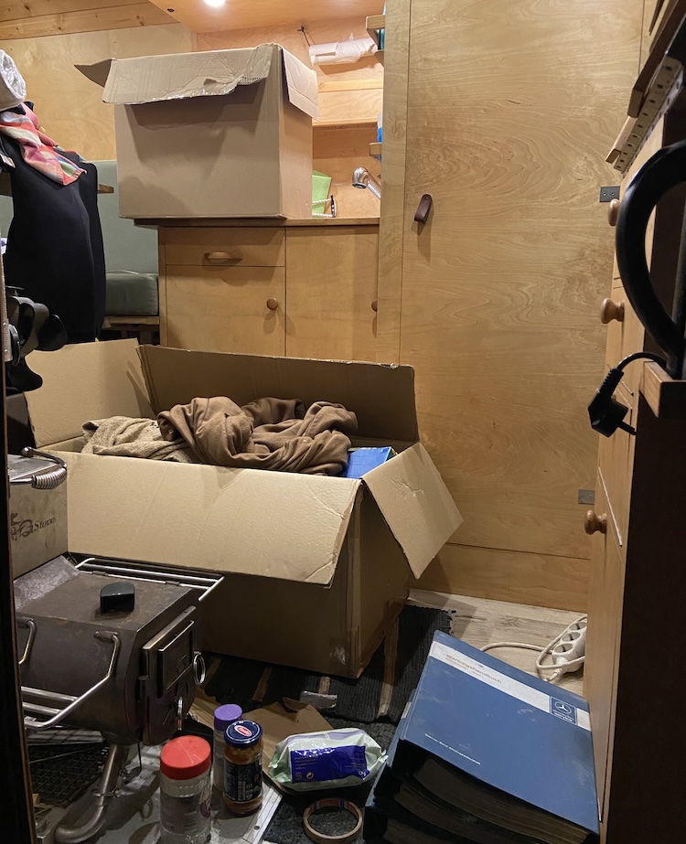
Realizing that ownership carried responsibility, possessing fewer things appeared more liberating to me. I was ready to part with my beloved Mercedes 508D. Given the perfect condition and high-quality conversion of the van, I had no doubts about finding a buyer willing to pay a fair price.
After packing a few boxes,
the van was emptied and ready for sale.
Oh, what a snug home on wheels it had been!
When entering the van for the last time, a flood of memories washed over me – this cozy home on wheels had witnessed countless beautiful moments.
Everything unfolded rapidly. In just a matter of days, the van was sold. I witnessed my van in motion for the first time, but this time from an external perspective - without me at the steering wheel. What an incredible journey!
Nevertheless, all of this felt right. As the van disappeared on the horizon, I felt a sense of relief, filling me with energy and motivation to persist in my ongoing endeavor — the conversion of the Mercedes 1113 truck into house on wheels, a project aimed at surpassing the legacy of the 508D once again.
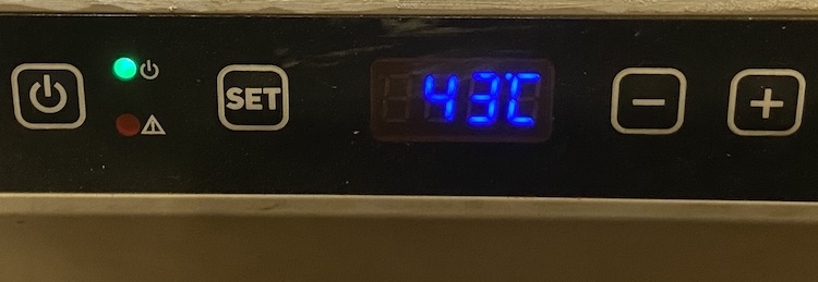
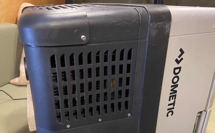
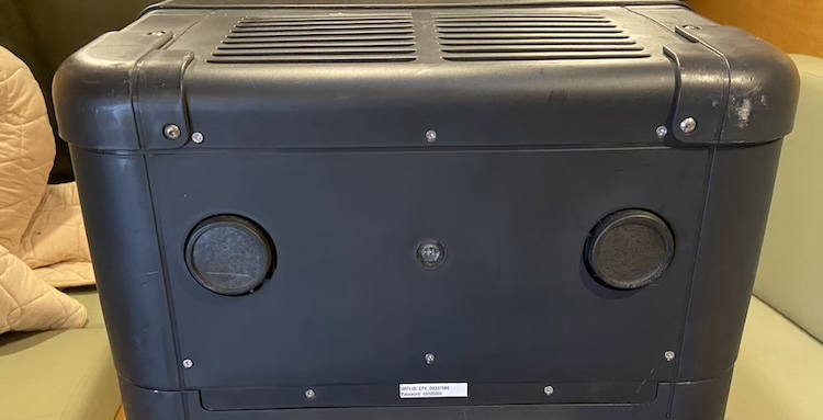
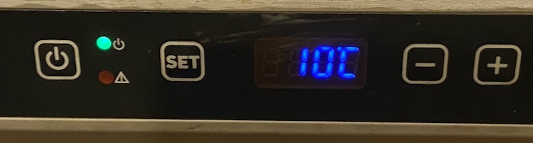
]]>Replacing the thermostat of a Dometic CFX 50 refrigerator2022-11-04T00:00:00+00:002022-11-04T00:00:00+00:00https://ruby-on-wheels.github.io/blog/replacing-thermostat-of-a-dometic-cfx-50-refrigeratorSuddenly, the compressor of my Dometic CFX 50 refrigerator in my Mercedes 508D was running continuously, even though the cooling compartment was extremely cold. To my surprise, the temperature displayed on the screen was 43 degrees Celsius, indicating a possible thermostat malfunction.
I was able to find a replacement thermostat in an online shop for a few euros and replaced it using the following steps:
First, I removed the 14 screws holding the vent on both sides (3 on each side),
and the (8) bottom,
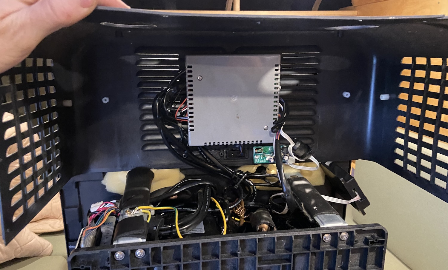
to carefully open the vent.
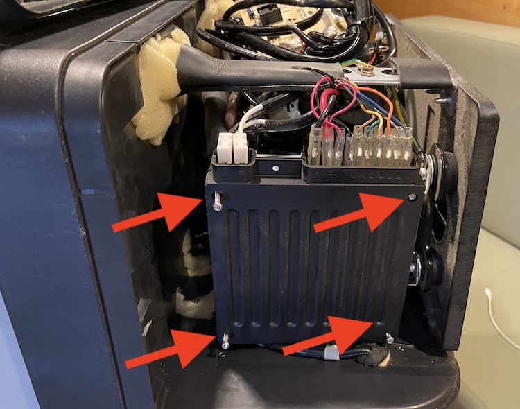
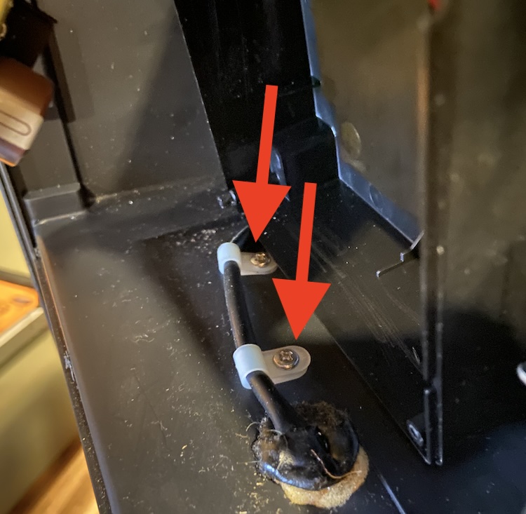
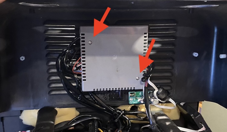
In order to remove the two screws holding the thermostat wire, I had to remove the compressor control module and its cover by loosening the screws holding the cover,
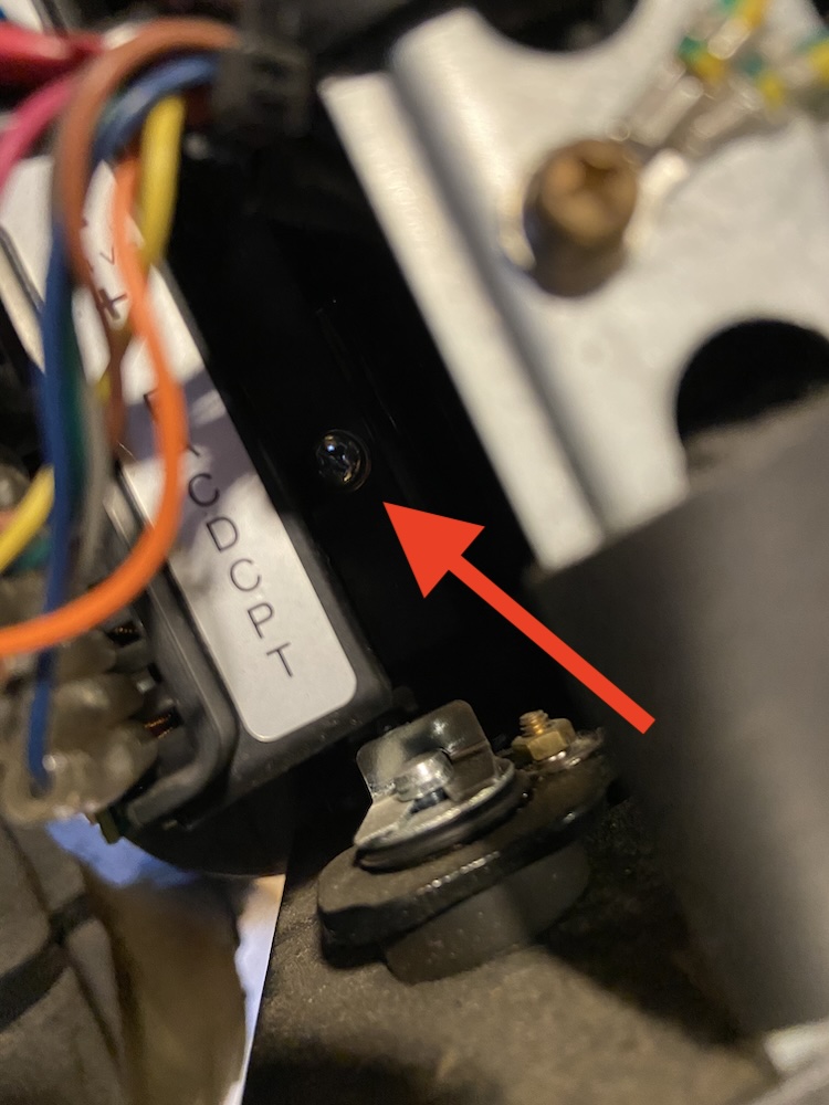
and the screw behind the module holding it.
After pushing the compressor control module aside, I was able to remove the screws holding the thermostat wire,
and could carefully pull the thermostat out of place.
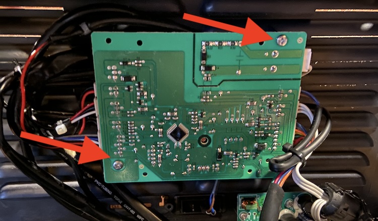
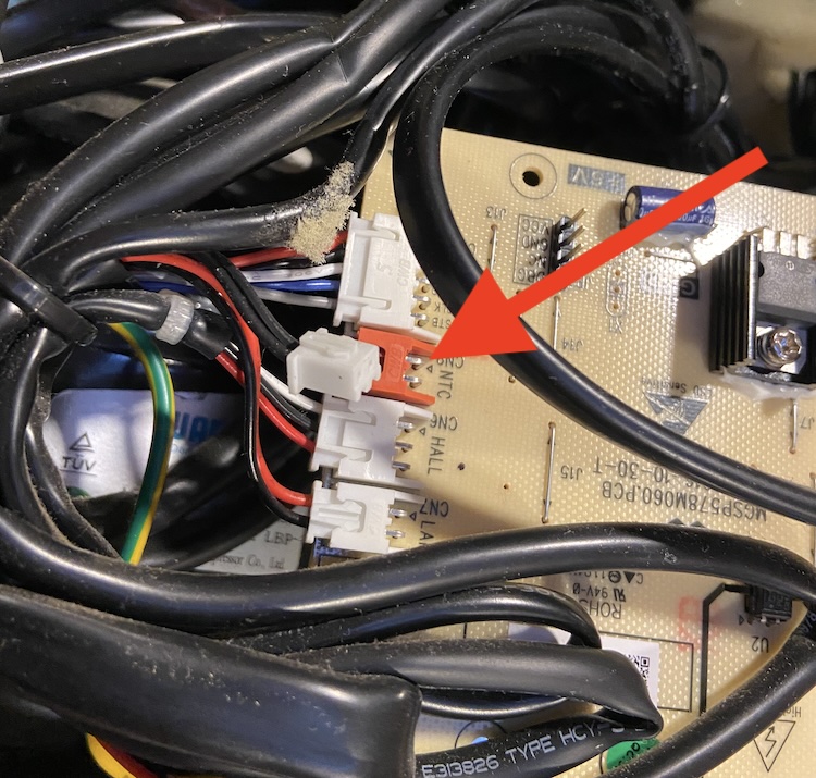
In order to disconnect the thermostat from the main PCB, I had to remove its cover by loosing the screws holding it.
Then the screws holding the main PCB could be loosened,
to finally disconnect and remove the thermostat.
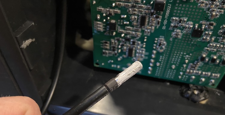
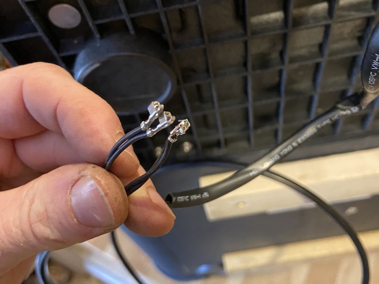
Unfortunately, the connectors of the new thermostat didn’t match with the connectors of the old one.
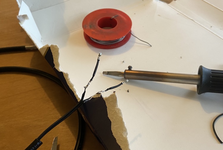
So, I simply soldered the connection of the old thermostat to the new one.
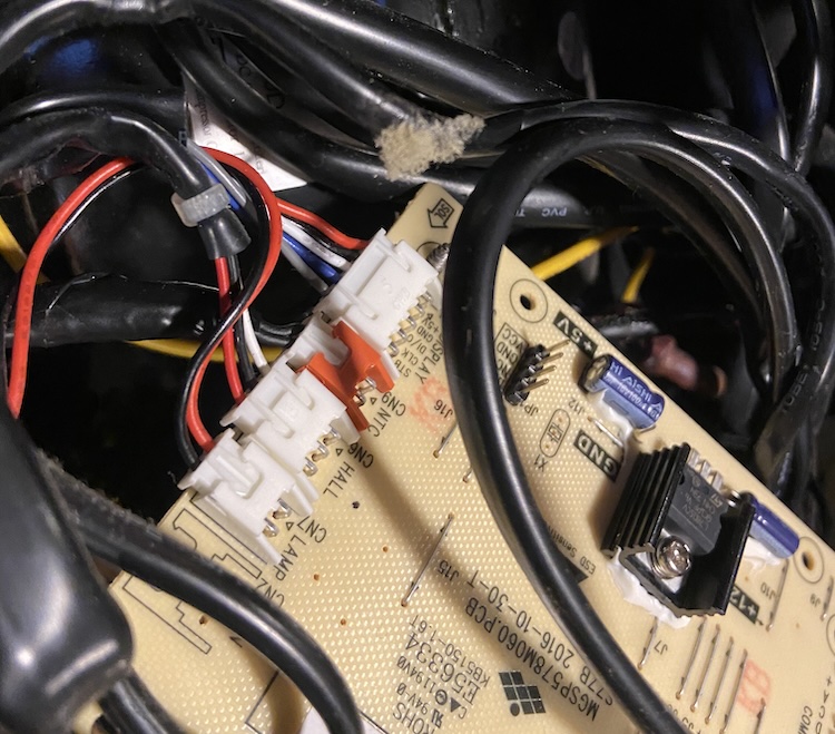
After stripping the wires, I attached the new thermostat to the main PCB and reassembled everything in reverse order.
The screen displayed the correct temperature and the refrigerator was working again. :tada:
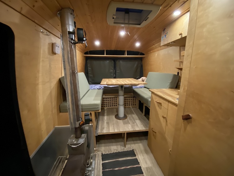
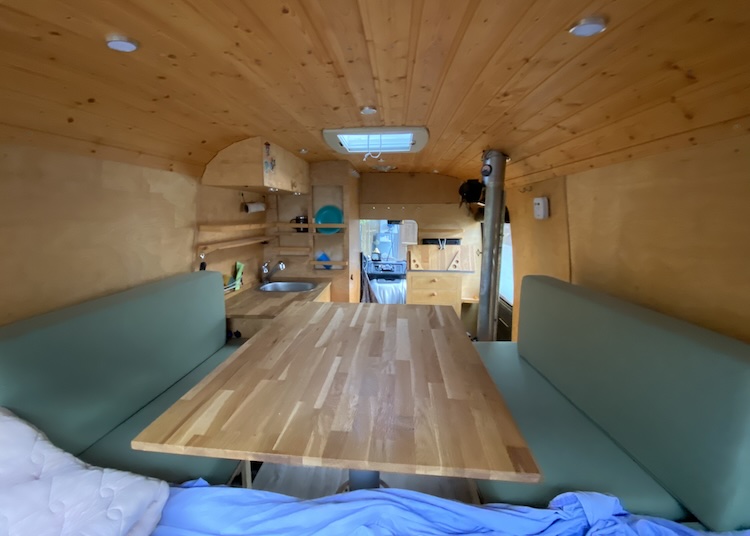
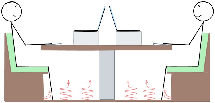
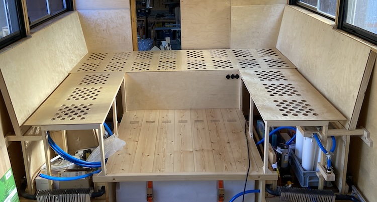
]]>Building the seating area2022-09-16T00:00:00+00:002022-09-16T00:00:00+00:00https://ruby-on-wheels.github.io/blog/building-the-seating-areaSimilar to all the other components that I built for my previous van, I identified areas for improvement in the seating arrangement as well: During winter, I frequently experienced cold feet as the space under the table lacked proper ventilation from the wood stove’s warm air. To achieve genuine comfort, I needed to insert a cushion or similar support between the vertical backrest and my back, creating a slightly inclined seating position. While working, I noticed a consistent habit of pulling the movable table towards my body, causing it to extend beyond the edge of the bench. In this setup, I could comfortably use my laptop while leaning against the backrest. It served well for solo use, but when accommodating a guest who wished to work facing me, either one person endured an uncomfortable position, or both found themselves in a suboptimal situation. Design-wise, it would have been more favorable if the table extended over the edges of the benches on both sides.
Refining the concept
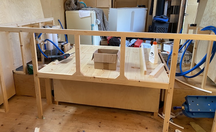
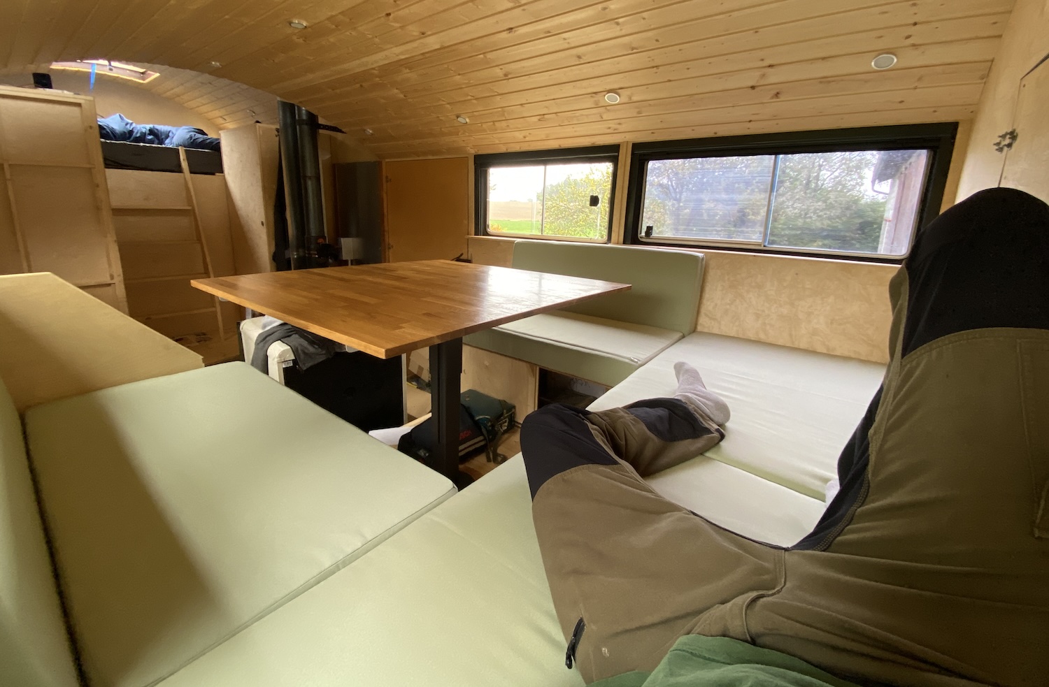
I incorporated these insights into the design of the truck’s concept, creating an improved and more spacious version of my van’s seating area: Positioned at the center, a large, sliding, and rotating table would provide enough space for two workstations. Following the layout of my van, a U-shaped seating area would surround the table. Slightly angled backrests on both sides would ensure the most comfortable seating position. In the rear section, a daybed would provide room for at least one person to relax or sleep without the need for any adjustments. To accommodate more guests, the table would be height-adjustable, expanding the daybed for up to four people. For optimal comfort during heating, warm air should circulate from the floor and seats, ensuring a warm foot area.
Building the double floor
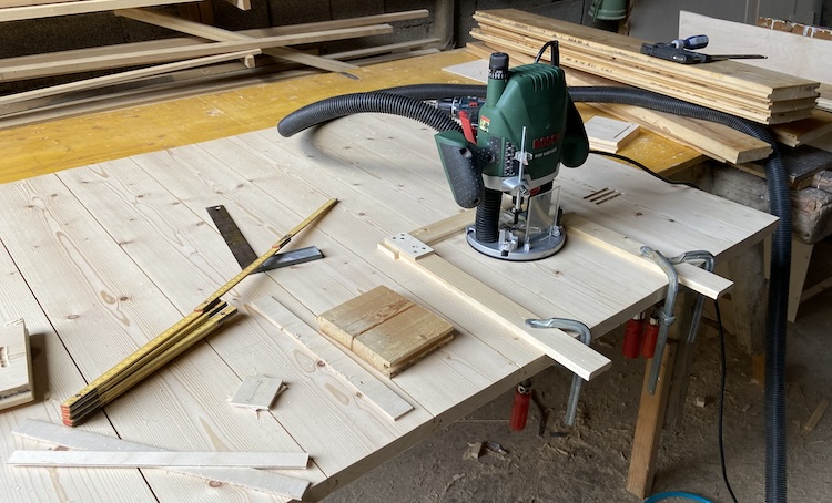
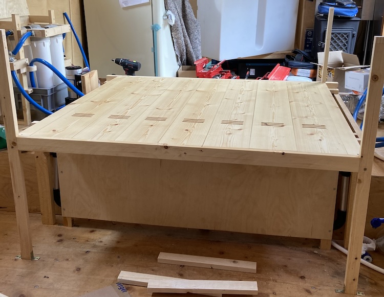
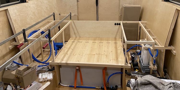
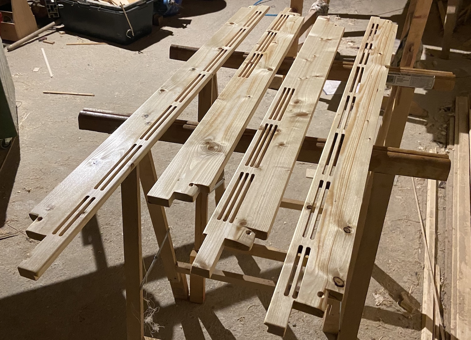
The water tank and the seating area would be divided by a double floor. To facilitate the flow of warm air from the ventilation shaft behind the water tank into the foot area, I milled slots into the thick tongue-and-groove boards forming the raised floor.
After oiling and sanding the floor panels, they elegantly concealed the water tank while offering vents for the warm, rising air.
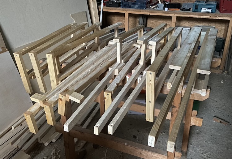
Constructing the seats
Starting at the rear, I constructed the basic framework for the seats,
and gradually progressed on the sides towards the front.
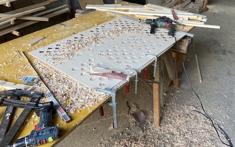
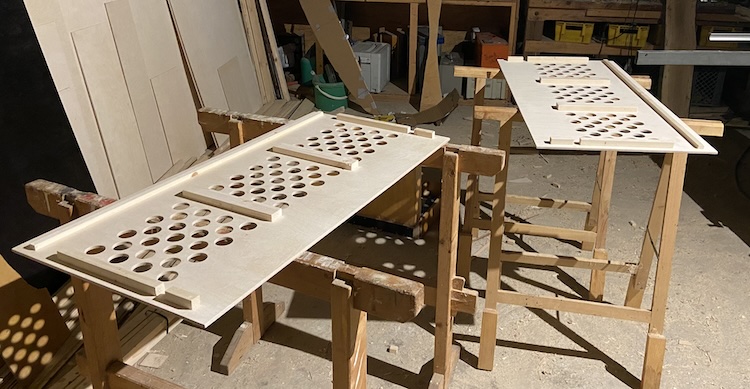
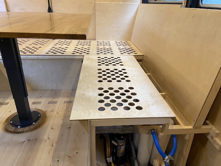
To prevent the formation of mold in the seat cushions, I drilled various holes into the removable covers of the seat surfaces.
For additional stability and smoother opening and closing, I glued additional slats to the underside of the covers.
After hours of drilling and sanding, the covers were finally completed.
Sloped covers on the side ventilation shafts would channel the warm air towards the footwell area beneath the table.
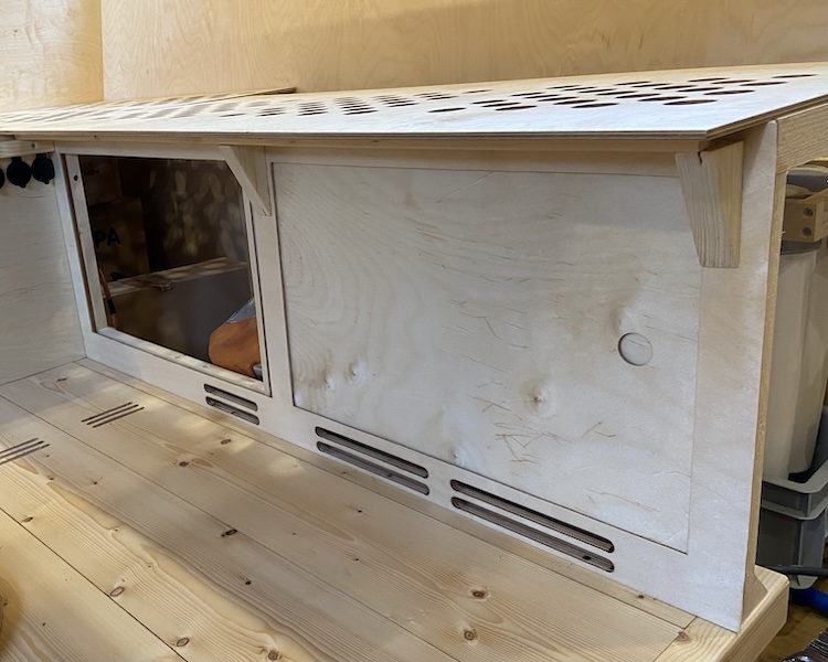
I constructed sliding doors for the front side of the benches.
When closed, they would prevent the stored items from slipping out.
And to access items, one could simply slide the doors to the side.
Installing the table
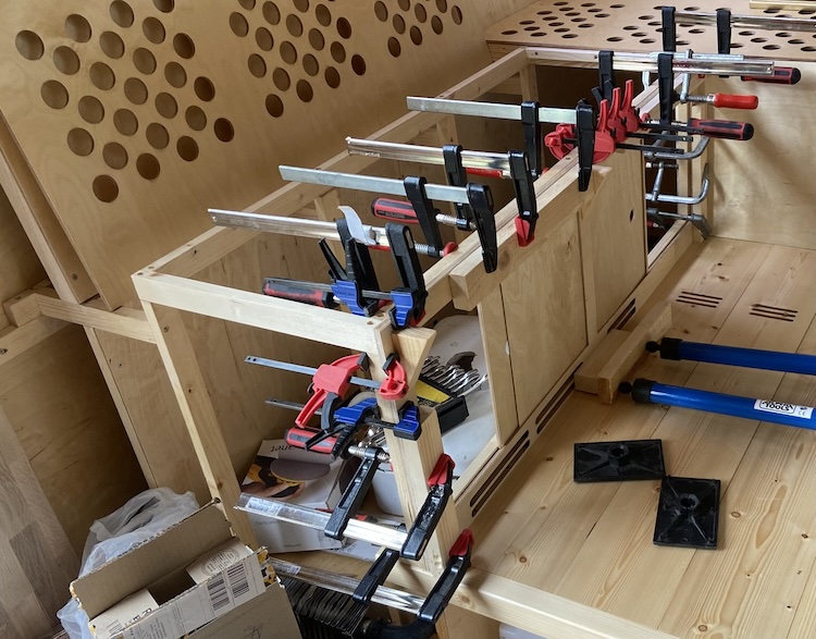
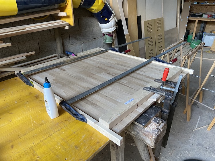
I assembled the large table top from multiple pieces of oak using large clamps.
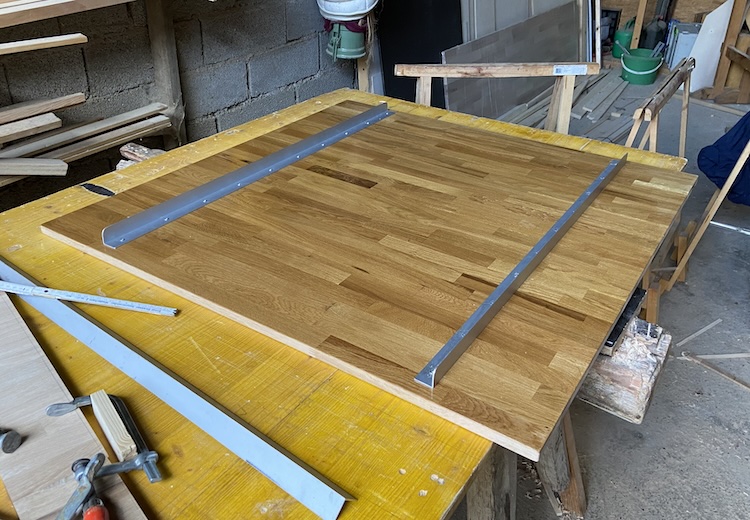
After sanding and oiling, I attached aluminum profiles to the underside to prevent the tabletop from warping due to changes in humidity.
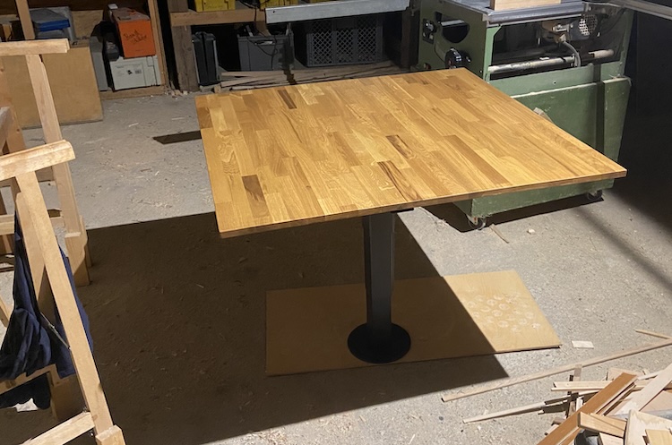
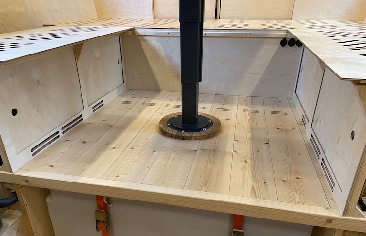
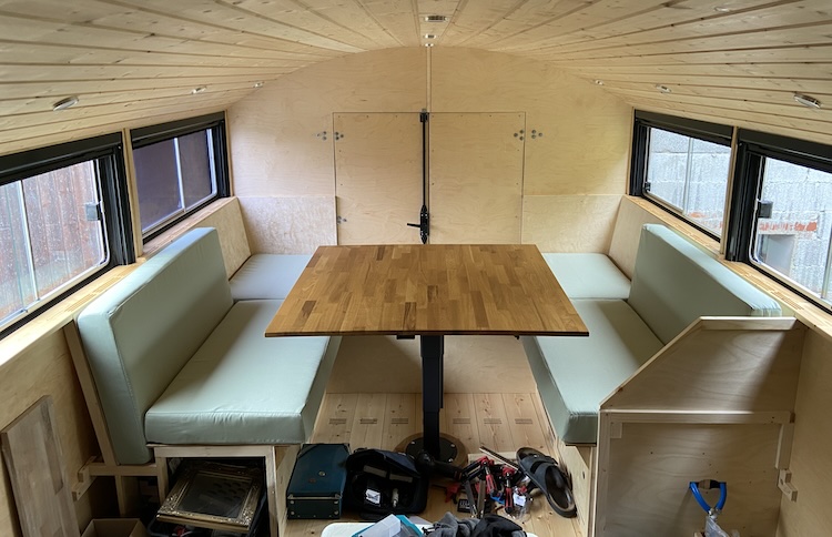
The beautiful oak tabletop made a robust impression on the sliding, rotating, and height-adjustable table leg.
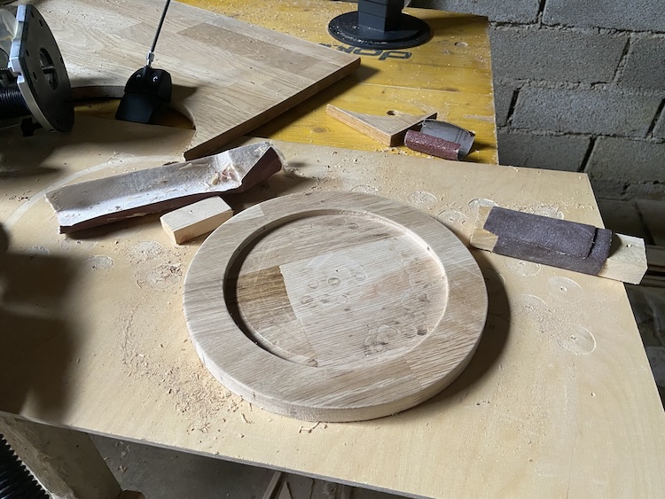
Similar to my previous van, I crafted a base from the same oak wood to securely mount the table on the double floor.
After sanding, oiling, and assembly, the construction made a beautiful impression on me.
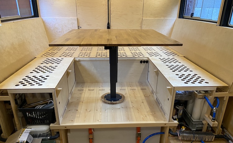
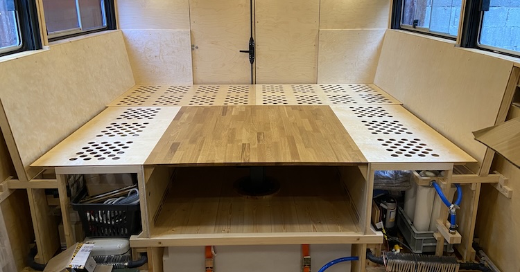
Transforming the seating area into a gigantic bed
In the seating mode, the seat covers were positioned forward to extend beneath the table, creating a gap for securing the back cushions.
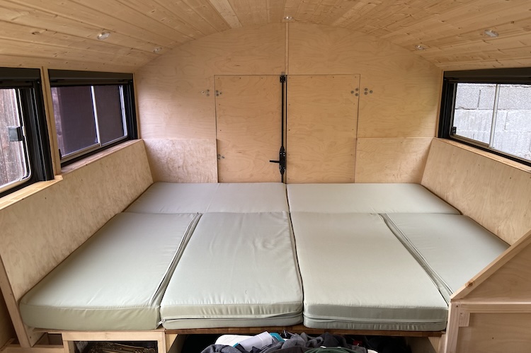
For the bed mode, the seat covers were shifted to the back.
This provided enough space in the middle to lower the table seamlessly.
With the cushions, this resulted in a gigantic and cozy guest bed.
With a few simple steps, the large bed could be transformed back into a comfortable seating area with a daybed, providing enough space for five to six people.
I was highly pleased as the cabin gradually transformed into a comfortable and cozy space.
]]>Installing the water tank, pump and filters2022-08-26T00:00:00+00:002022-08-26T00:00:00+00:00https://ruby-on-wheels.github.io/blog/installing-the-water-tank-pump-and-filtersOverall, I was quite satisfied with the water system I had built for my previous van. However, I had discovered areas for improvement over the years: The filling nozzle went directly into the tank, meaning I always had to fill it with clean water to prevent contamination. During long stays of several months in locations with access to a well or a spring, I sometimes wished to be able to pump water directly into the water system of the cabin without having to fill the tank manually with a watering can. As I hadn’t installed a separate drain valve, emptying the tank required pumping the water through the entire system, including the filtration unit. And, of course, it would have been great to be able to store more than 90 liters.
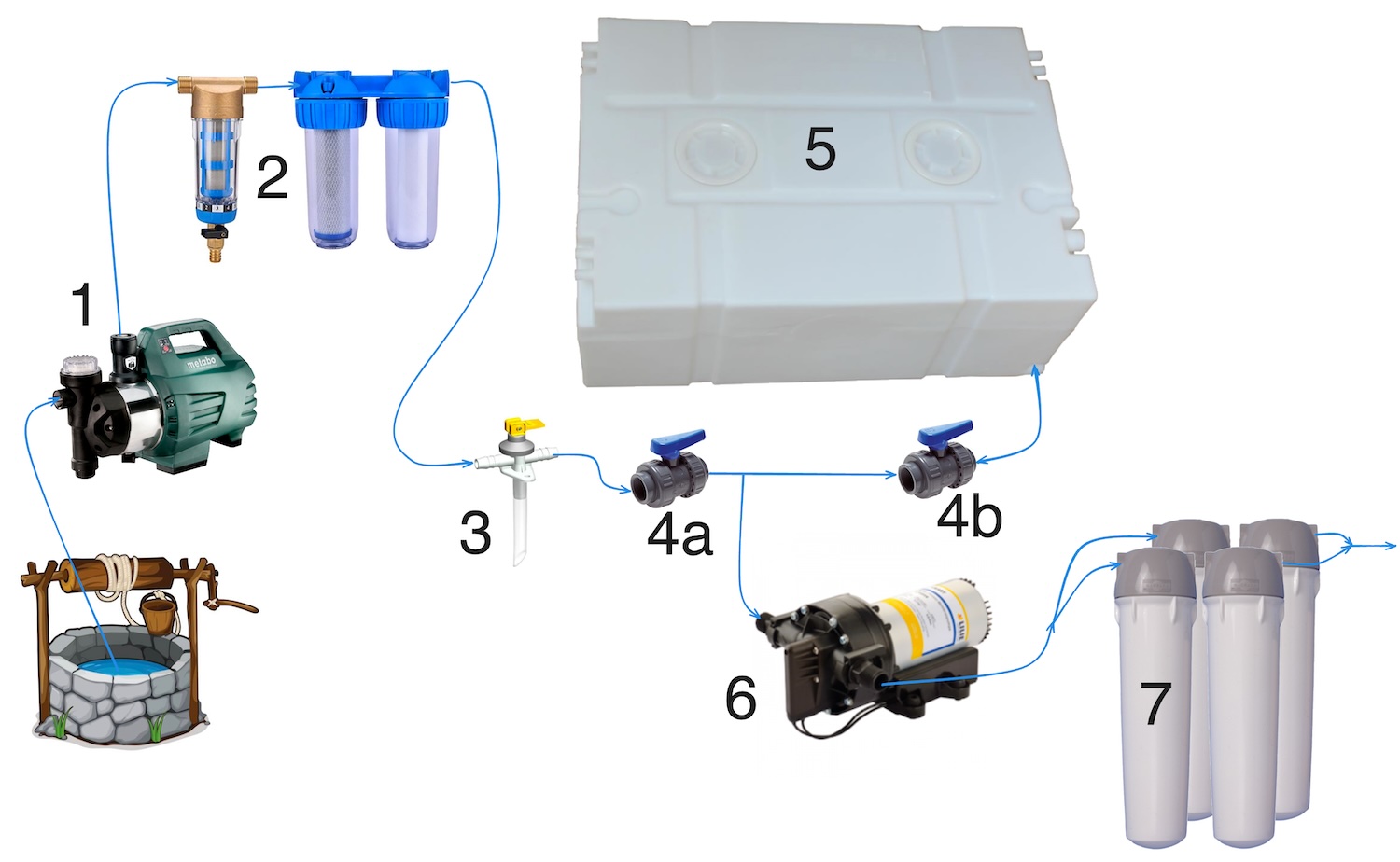
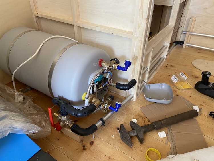
For the truck, I envisioned an upgraded design featuring an external pump (1) capable of drawing water from deep wells and pushing it through a filtration system (2). Two control valves (4a, 4b) would allow to either direct the purified water into the cabin’s water system or store it in a sizable 200-liter tank (5), which could be emptied using a separate drain valve (3).
The control over the water flow would be as follows:
4a
4b
Effect
open
closed
Water would get pushed directly into the water system of the cabin.
open
open
Water would get pushed into the tank (5) or drained through the open valve (3).
closed
open
Water would get drawn out of the tank by the internal pump (6) into water system of the cabin.
The remainder of the setup was designed to mirror that of the van: a pump pushing water from the tank through a filtration system, ensuring the removal of germs, chemicals, and unpleasant tastes.
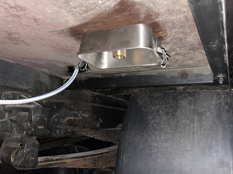
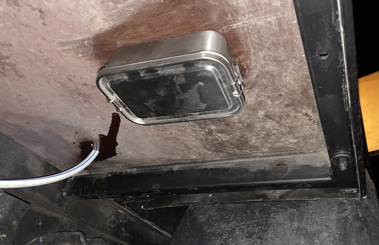
Mounting the connector for the external pump
I drilled two holes in the floor behind the right rear wheel. One for the drain valve and one for the connection of the external pump.
To protect the connector from dust and dirt stirred up during travel, I repurposed an available stainless steel lunchbox.
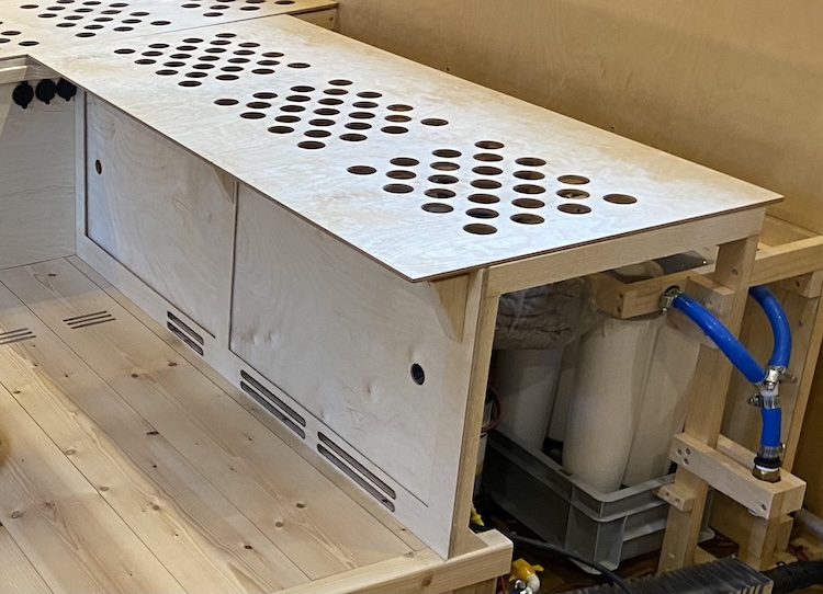
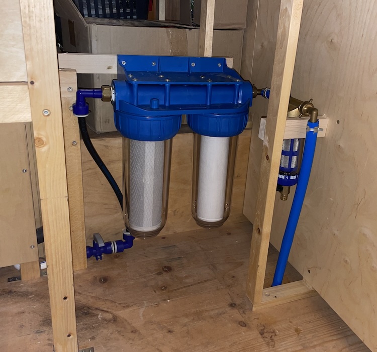
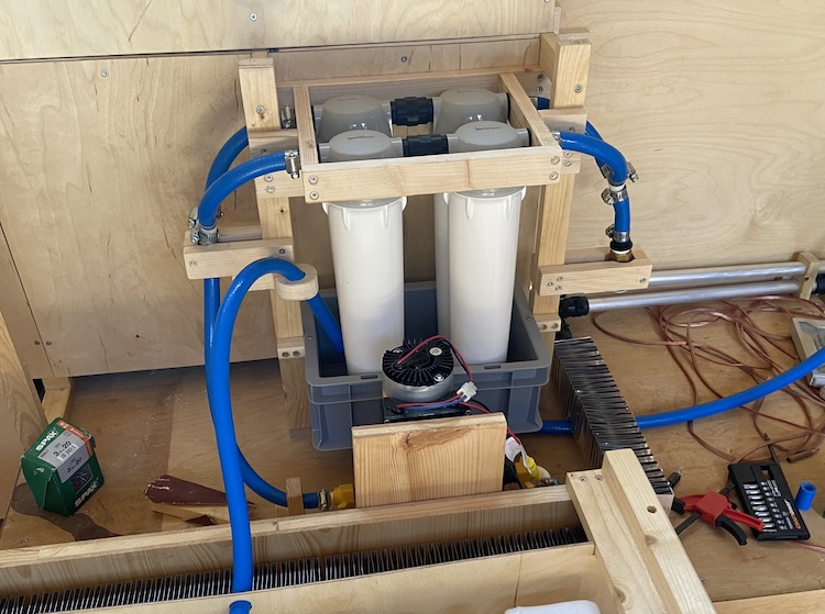
Setting up the filters
Inside the cabin, I installed a washable 40 micron pre-filter followed by an activated carbon and a 0.3µ ceramic filter. The drain valve followed the filters. This arrangement allowed me to flush the filters after a long period of inactivity by closing the valve 4a and opening the drain valve.
To prevent potential contaminants in the tank from entering the plumbing system, I implemented an additional filtering system after the pressure water pump. As the pump in the cabin had slightly less power than the external pump, I chose to arrange two rows of filters in parallel to enhance the flow.
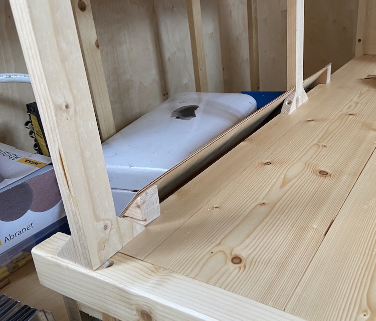
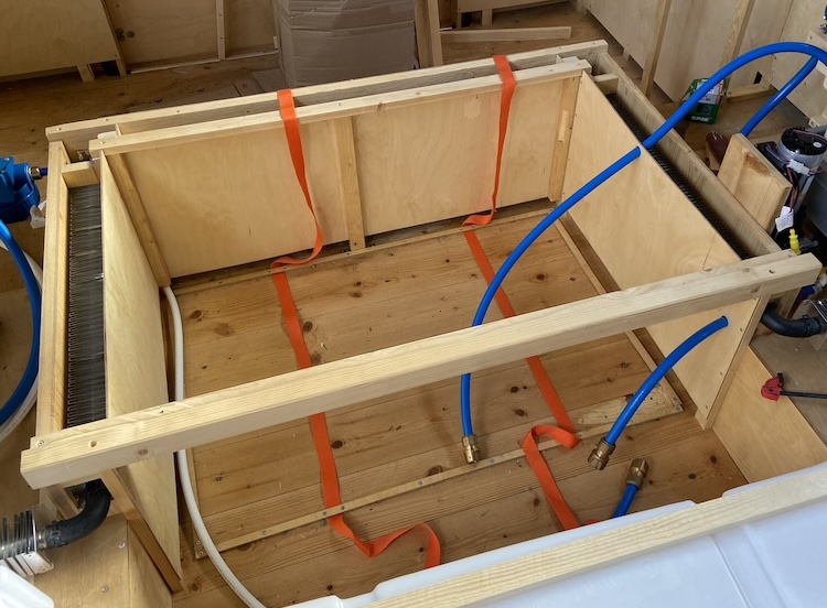
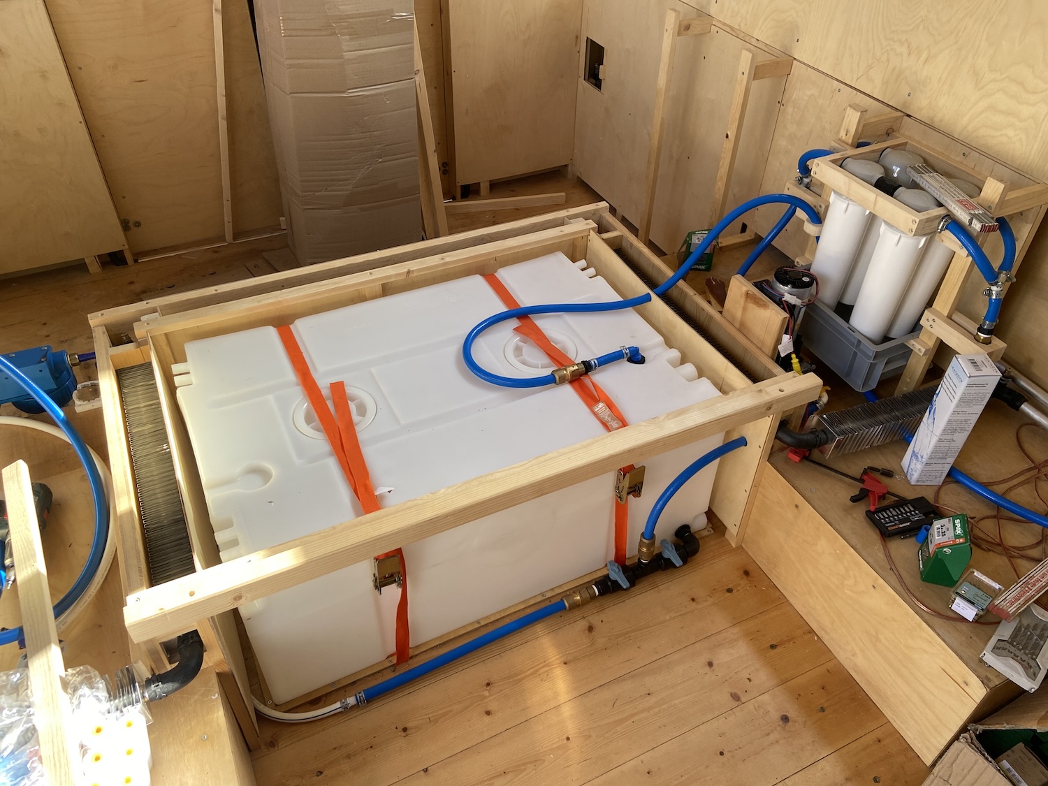
Installing the water tank
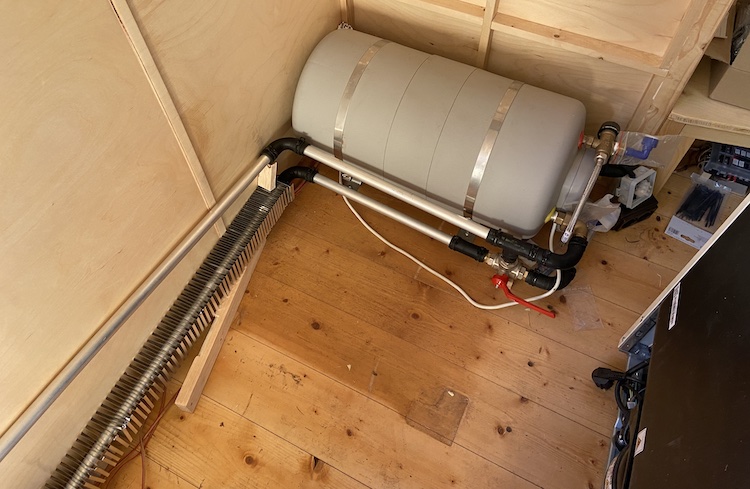
To anchor the 200-liter water tank to the floor between the ventilation shafts, I affixed two tension straps and small braces that firmly secured the tank in place, preventing any sliding.
Thanks to quick couplings, connecting the tank to the pre-filters, post-filters, and the vent and overflow hose was quick and easy, simplifying the regular cleaning process.
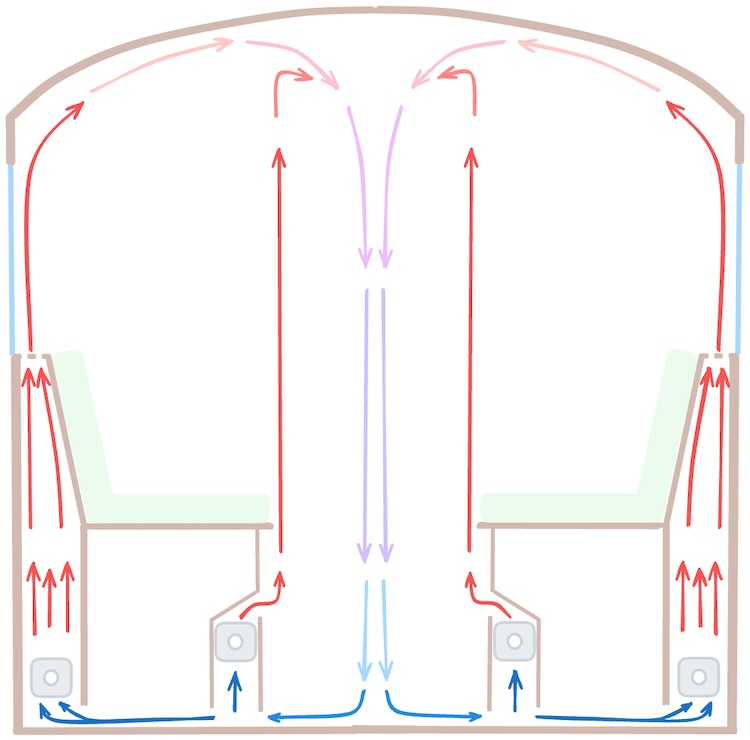
]]>Building heating ventilation shafts2022-08-24T00:00:00+00:002022-08-24T00:00:00+00:00https://ruby-on-wheels.github.io/blog/building-heating-ventilation-shaftsAfter laying the heating pipes and installing the radiators, I further refined the heating system by building ventilation shafts to facilitate airflow within the cabin. Cold air from the floor would be drawn into the shafts and warmed by the radiators. By narrowing the ventilation shafts upwards, the chimney effect would be improved, resulting in an additional acceleration of the warm, rising air.
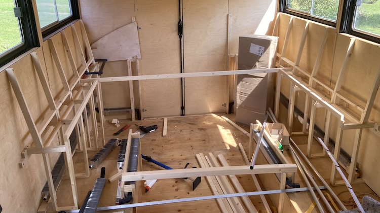
Building the foundational structure
The shafts would be seamlessly integrated into the seating area, so I started with the construction of a robust foundational structure using spruce slats.
After oiling and preparing all the parts, I proceeded to mount them within the cabin.
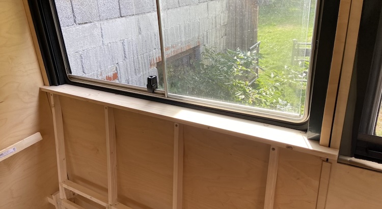
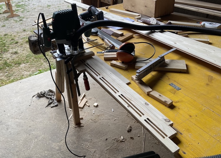
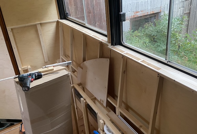
Crafting the window sills
I precisely fitted matching window sills from spruce slats that would sit on top of the fundamental structure.
I used my router to mill slots into the window sill, allowing the warm air to flow effectively through it and rise as close to the window as possible.
I was satisfied with the initial prototype, so I proceeded in a similar fashion with the remaining window sills.
Once finished sanding and oiling, I mounted the window sills in their designated positions under the windows.
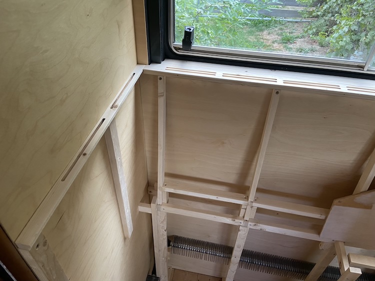
On the rear wall, where there were no windows, I attached slightly narrower strips.
Covering the shafts
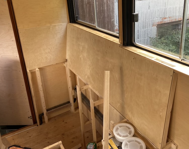
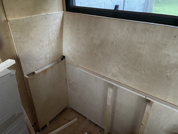
Subsequently, I constructed and installed the backrests, which served as a cover for the inclined part of the ventilation shaft.
For the lower, straight sections, I built a small sliding door into the covers.
Through the small maintenance sliding door, access to the ventilation valve for the radiators positioned at the highest point in the rear section was available.
When the door was closed, the warm air would flow nicely upward through the openings.
The system was ready for its first practical test! Using the flame of a lighter, it was easy to observe how the warm air flowed upward from the slots in the window sills.
Building ventilation shafts around the water tank
Previously, in my van during winter, I would occasionally observe condensation forming in poorly ventilated areas on the wall of the water tank. To prevent this, I built additional ventilation shafts around the tank.
The warm air rising from these shafts would then function as heating for the area above the tank and beneath the table.
]]>Installing a hydronic heating system2022-08-08T00:00:00+00:002022-08-08T00:00:00+00:00https://ruby-on-wheels.github.io/blog/installing-a-hydronic-heating-systemThe wood stove that I installed into my Mercedes 508D did a great job keeping the van warm and cosy. However, when spending a few months in Northern Europe, I also noticed a few problems with the heating system in my van: The heat didn’t spread evenly across the cabin. In particular, the lower corners in the back of the van under the seats were usually much colder than the open space around the wood stove. During long lasting wet periods, I had a hard time keeping these corners dry to prevent mold from forming. I also had to go without hot water in the northern hemisphere winter because there wasn’t enough solar energy to run my work laptop and electric boiler, which seemed counterintuitive: hot showers in summer but cold showers in winter?!?
Improving the concept
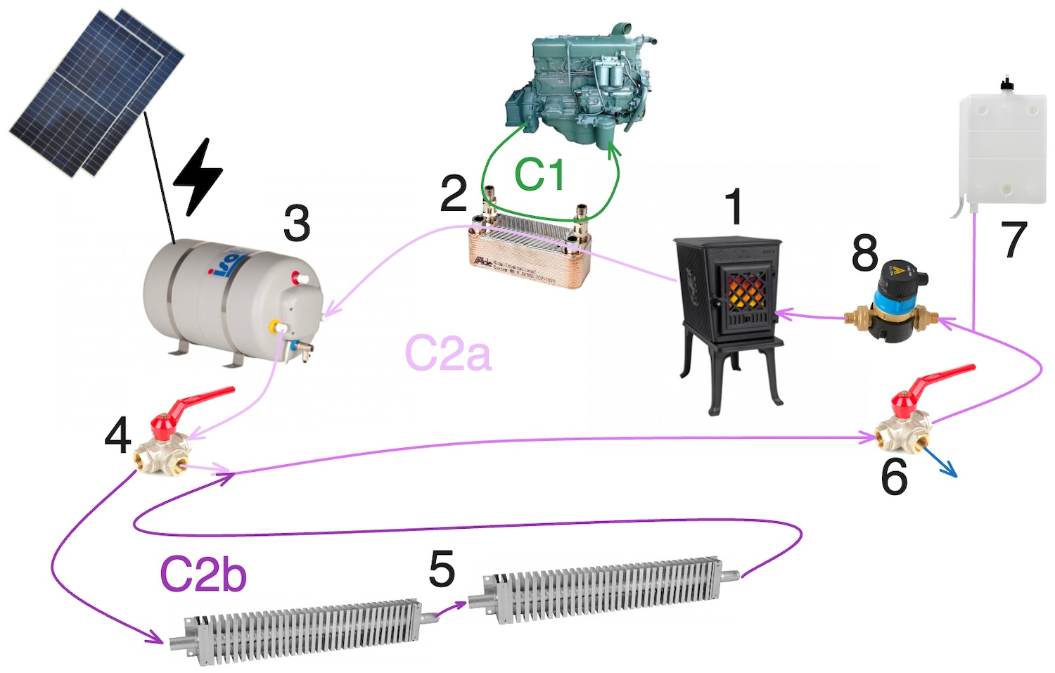
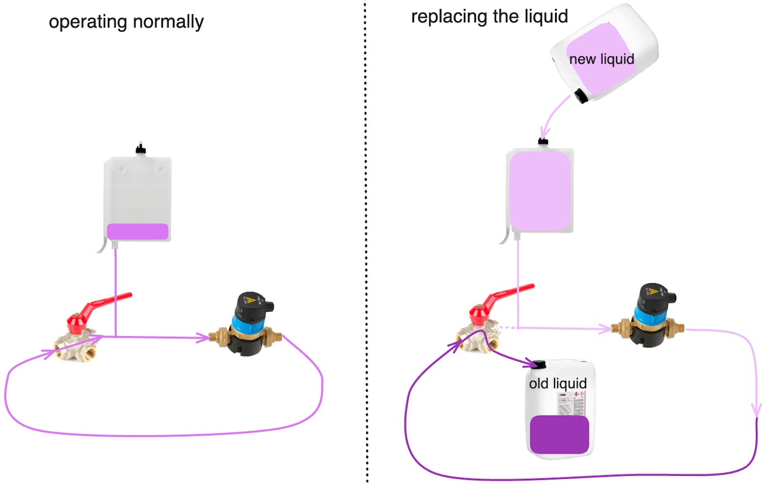
To overcome the shortcomings of the previous heating system in my van, I developed a new concept for the truck: a hydronic heating system with multiple sources of heat: a wood stove (1), the engine’s cooling system through a separate heat exchanger (2) and an electric boiler (3). With the help of pipes and radiators (5) I would be able to transport the heat into corners and places that were out of reach of the wood stove. Exchanging heat between the cooling circuit of the engine (C1, green) and the heating system of the cabin (C2, purple) would also allow me to preheat the engine with the wood stove on cold days for better starting ability.
I divided the heating circuit of the cabin into two parts. A short circuit (C2a, bright purple) only connected the heat sources, which would allow me to heat the water in the boiler on warm days without heating the cabin unnecessarily. A three-way valve (4) would allow me to enable an extended circuit (C2b, dark purple), which additionally included a series of radiators placed in all the corners of the cabin to improve the thermal ventilation in these hidden places.
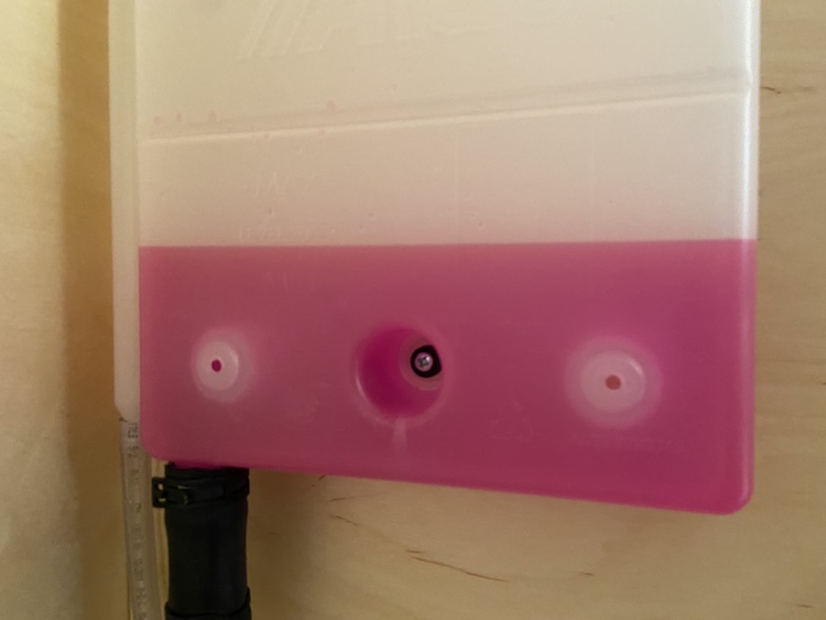
A flexible expansion tank (7) with an air outlet would be mounted at the highest point of the circuit. It was meant to equalize the pressure in the circuit. It also served as inlet for filling the liquid into the heating system. An additional three-way valve (6) mounted before the expansion tank and pump (8) would allow to easily top up, replace or remove the heater liquid:
Using the wood stove as a heat source
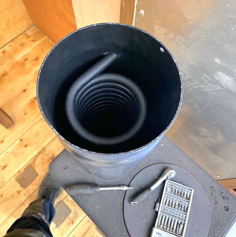
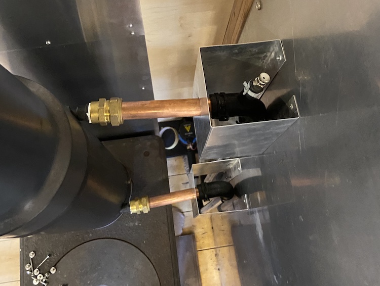
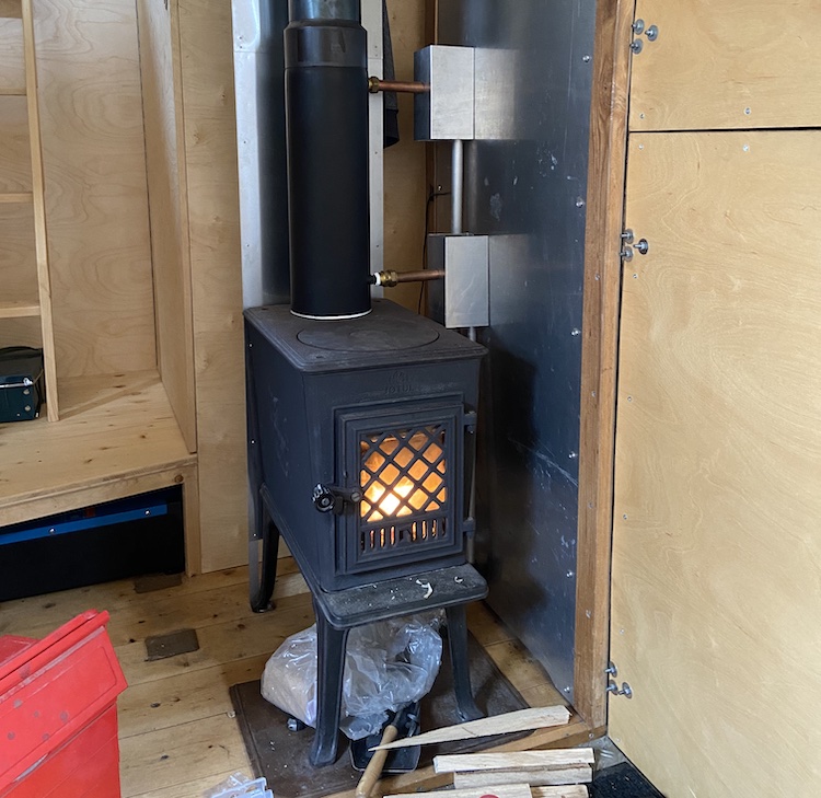
To heat the liquid with the wood stove, I installed a stainless steel coil in the chimney directly above the stove.
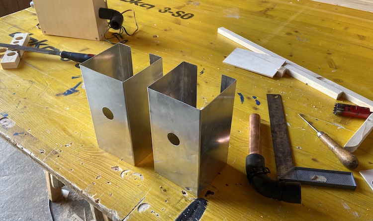
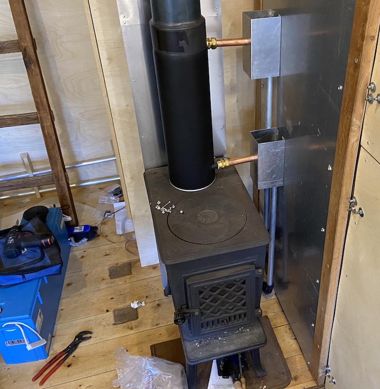
I installed a vent valve behind the outlet of the heat exchanger in the chimney. Since there wasn’t a lot of space between the wall and the chimney, I decided to build aluminum heat shields.
Mounted behind the shields, the rubber angle hoses were protected from the stove’s heat radiation.
By opening the vent valve from the top, air could be easily removed from the heating system.
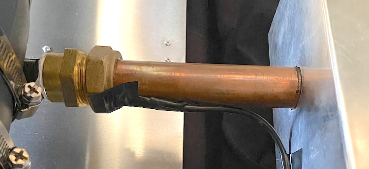
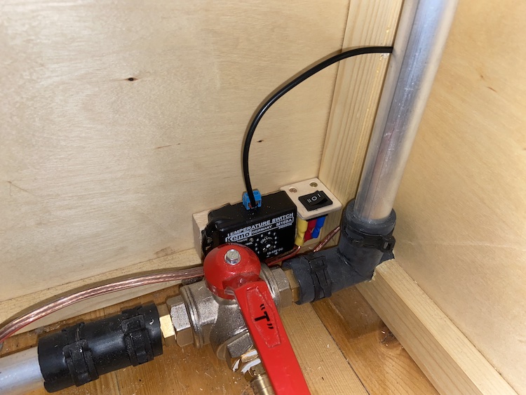
Permanently running the pump seemed like a waste of electricity. The cooling of the smoke while lighting a fire when the chimney was still cold also had a negative effect on the chimney draft, so I attached a heat senor on the outlet of the heat exchanger.
A tiny microcontroller connected to the sensor automatically switched on the pump a few seconds before the liquid in the pipe would begin to boil and switched it off as soon as the pipe would cool down to about 40 to 50 degrees Celsius. Additionally, I installed a switch that would allow to manually override the microcontroller by turning the pump on or off.
Installing the other components
The three-way service valve, expansion tank and heat exchanger for the engine’s cooling system fit nicely into the wardrobe behind the wood stove.
I placed the 25 liter electric boiler right in front of the bathroom to keep the hot water pipes as short a possible.
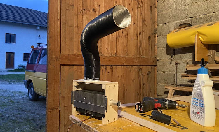
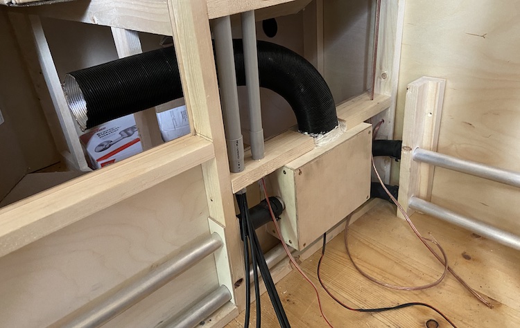
To heat and dry the bathroom, I built a fan supported radiator.
Mounted into the bottom of the cubicle wall, the fans would blow air through the radiator into the bathroom to further increase the radiator’s performance.
Installing the radiators in the living space
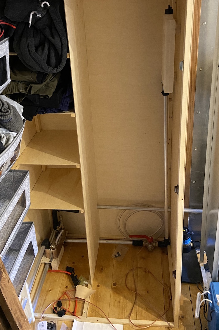
Once the short circuit was installed, I layed the pipes for the extended circuit for heating the living space.
I routed a duct in the floor at the back of the cabin. Embedding the heating pipe directly in front of the back door would have a positive thermal effect on the cold air that might potentially come in through the door gap.
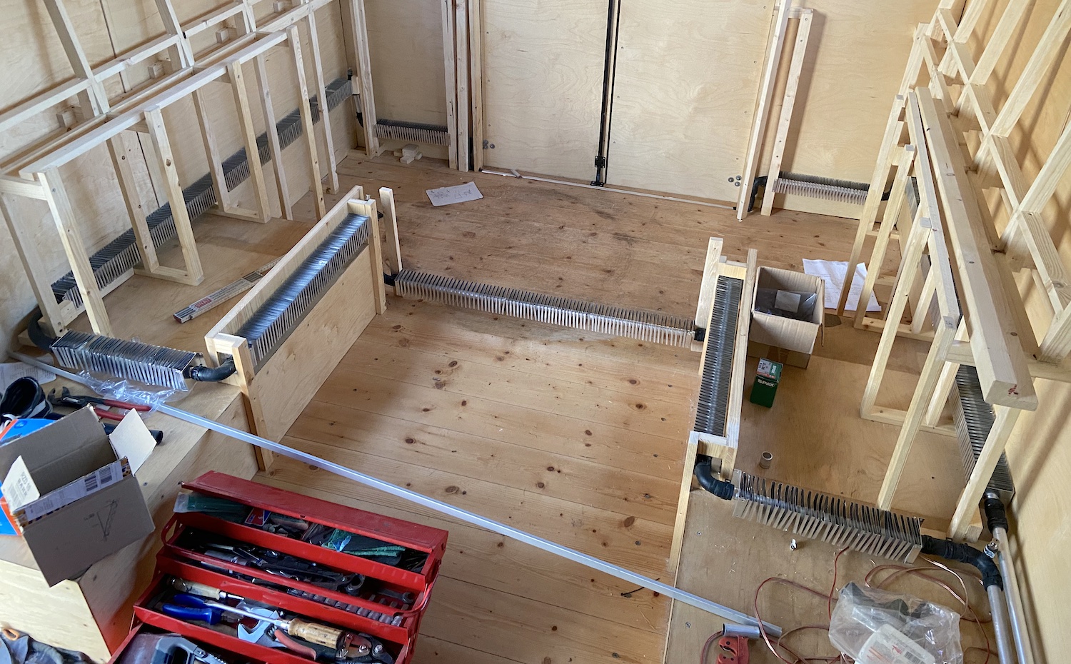
Step by step, I installed all the radiators and vent valves in the places where I planned to build the seating area and install the water tank.
Once all pipes were layed, I could finally fill the liquid (glycol) into the system.
After running the pump for a couple of hours and releasing all the air through the vent valves, the system was ready for its first test!
Shortly after lighting the fire, the pump began pumping fluid through the system. The feeling of warmth in the radiators brought a big smile to my face. I was really happy to have turned my new concept into reality! :fire: :tada:
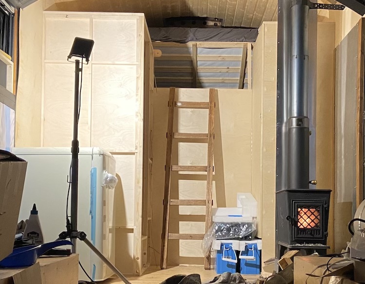
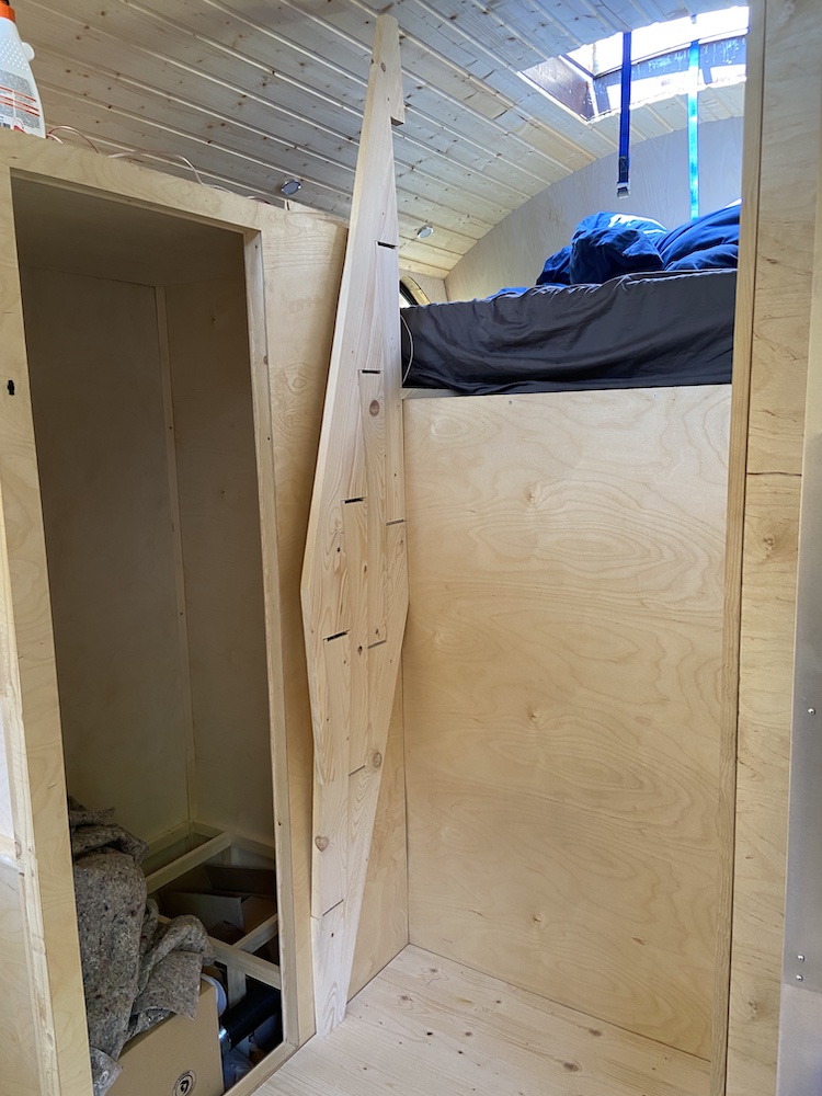
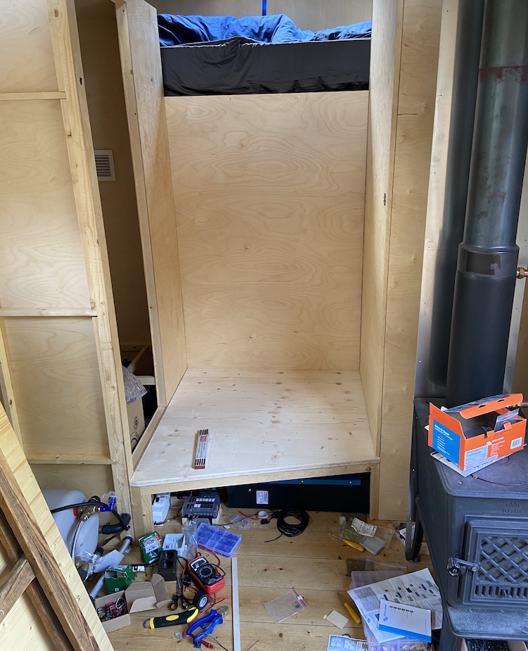
]]>Building foldable stairs2022-07-07T00:00:00+00:002022-07-07T00:00:00+00:00https://ruby-on-wheels.github.io/blog/building-foldable-stairsBefore setting up the electrical system, I used a simple wooden ladder to access the sleeping area of the truck.
I didn’t like the ladder. It was quite steep, so leaving the sleeping area was a little inconvenient. It also blocked the area in front of the wardrobe, so each time I wanted to open the door of the wardrobe, I had to move the ladder and make sure it wouldn’t slide away. I also had to stow away and secure it while driving.
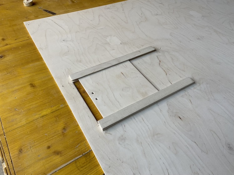
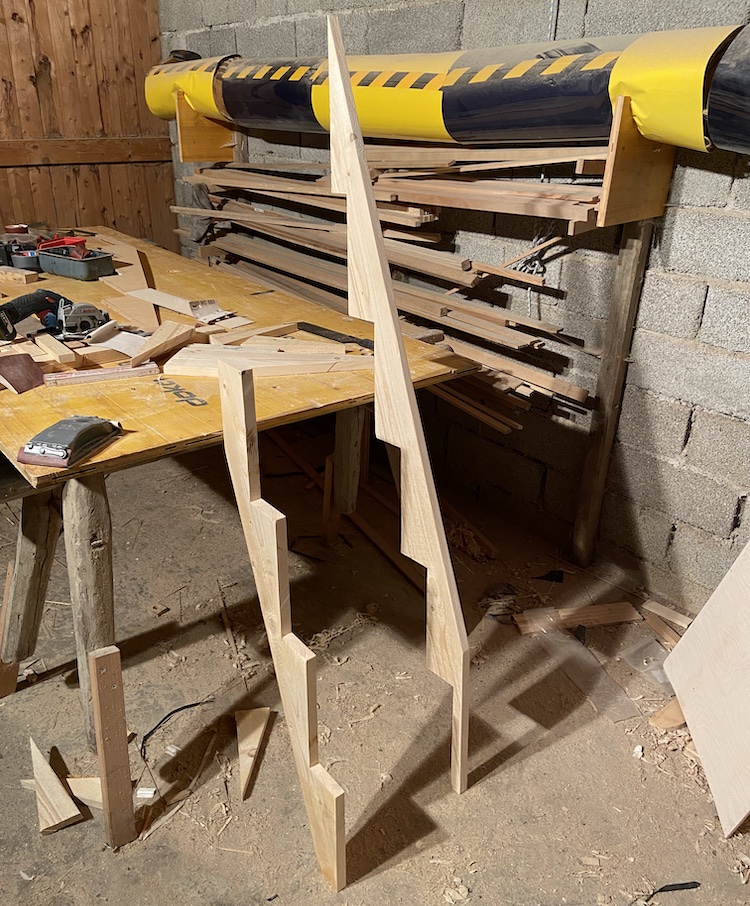
I really liked the idea of a foldable staircase that would be mounted to the wall and provide the possibility of clearing the space in front of the wardrobe easily. Calculating the angles and dimensions of the cut-outs challenged my geometry skills but after sketching down my thoughts on a piece of paper and building I little prototype, I was finally able to prepare the side panels of the stairs.
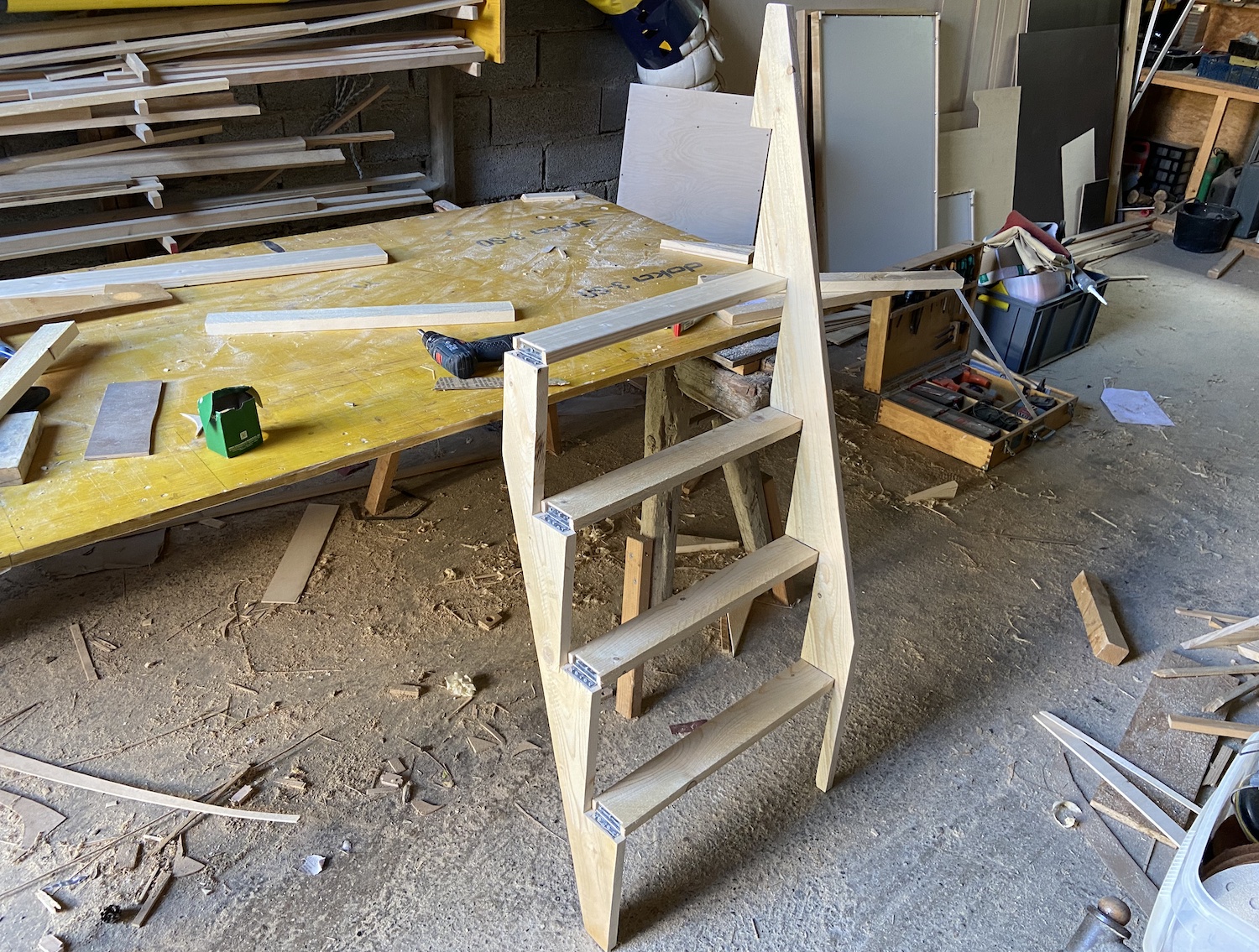
I mounted the steps with hinges on the side panels, which made it possible to fold the entire staircase.
I screwed the left and shorter side panel to the wall of the bathroom cabin. The right and higher side panel loosely rested on the top and bottom floor.
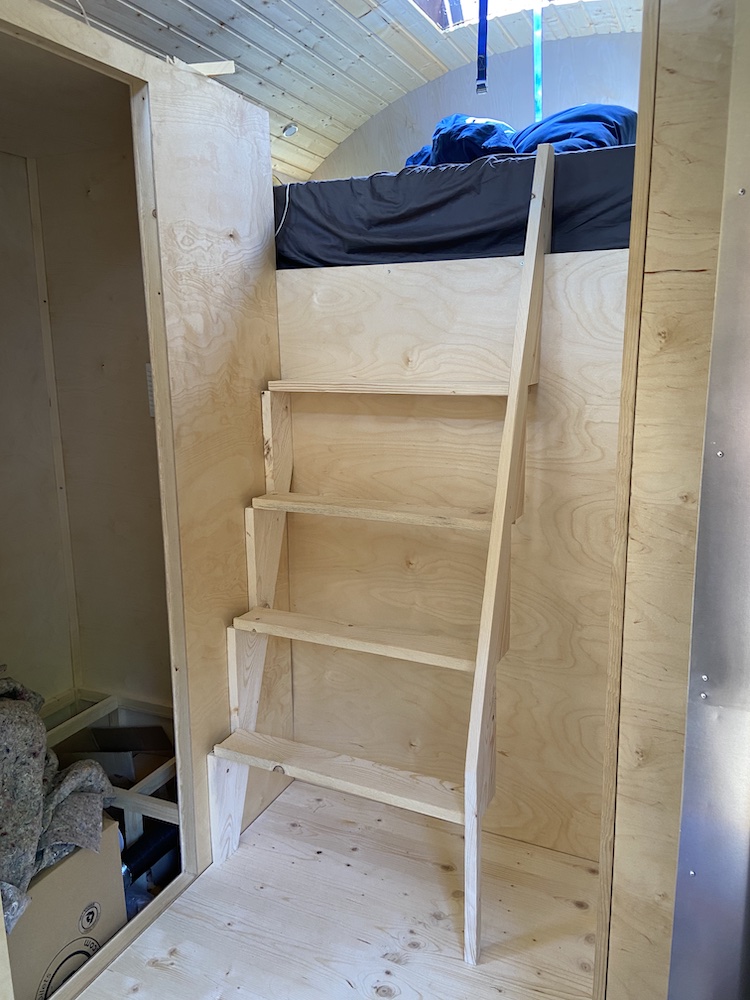
The construction provided enough stability to comfortably move the stairs up and down and could be easily folded to the side to clear the space in front of the wardrobe.
I really liked the new stairs. Moving in and out of the sleeping area became much more comfortable, the wardrobe was easy to access and the stairs were permanently secured.
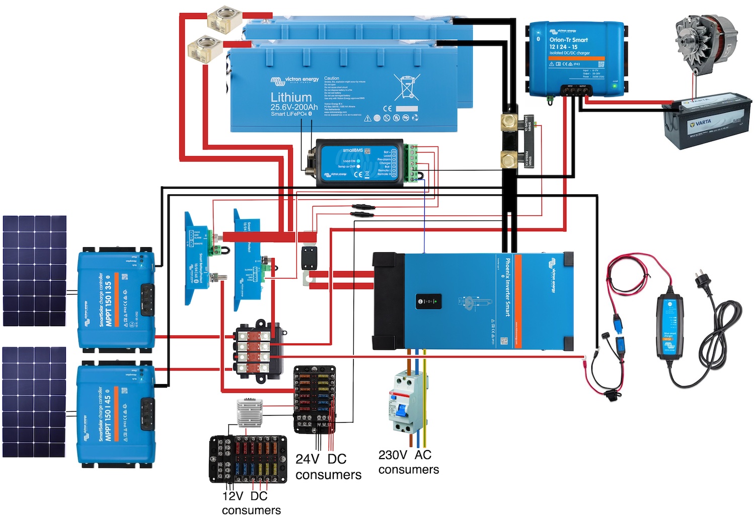
]]>Wiring the electrical devices2022-07-06T00:00:00+00:002022-07-06T00:00:00+00:00https://ruby-on-wheels.github.io/blog/wiring-the-electrical-devicesAfter installing the solar panels, I focused on the electrical system of the cabin. I envisioned a setup comparable to a regular house providing sufficient capacity during the winter, several 230V AC, 24V DC, 12V DC and USB power outlets for all kind of consumers. I also wanted to be able to operate professional power tools without having to worry during cloudy days, so the setup I envisioned for the truck was meant to become a little more complicated than the one of my van.
Picking the components
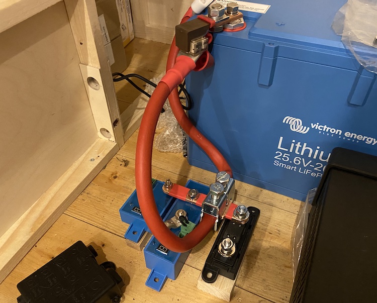
Similar to how I had increased the total power of the solar system by a factor of four, I also bought four times the battery capacity. I increased the basic voltage from 12V up to 24V to cut the required cross-section of the cables in half. While my van was equipped with a 200Ah 12V lithium battery, I had ordered two 200Ah 24(25,6)V lithium batteries which resulted in a total capacity of 10.2kWh for the truck.
The 2200Wp solar system was meant to be the main source of power. I planned to operate two solar charge controllers in parallel. One for the five solar panels on the front roof, which were connected in series and able to deliver about 1000W at a voltage of about 100V. And another charge controller for the six solar panels on the back roof, which were also connected in series and able to deliver about 1200W at a voltage of about 120V.
For unexpected emergencies, I wanted to be able to charge the 24V batteries by connecting the truck’s 12V alternator through a DC-DC charger or an external 230V power source.
I bought most of the electrical components right after starting the truck project in 2021. I luckily placed the orders just a few months before we faced a global energy crisis that resulted in high prices and low availability of products related to solar energy. Even before the crisis, certain devices were hard to get, because global supply chains were heavily interrupted by the effects of the Corona pandemic.
I was quite happy with the 12V DC boiler in my van, however all DC boilers I could find were out of stock and not deliverable. After sending several emails and making a bunch of phone calls, I finally gave up on a DC boiler and managed to get hold on a left-over 230V AC boiler that suited my needs.
Because of the boiler, I had to rely on a permanent 230V AC system, so I decided to switch from a 12V compressor cooler to a regular 230V refrigerator. Domestic refrigerator offered a separate freezer and were almost six times cheaper than coolers optimized for campers. I had enough space in the truck and had to setup a proper 230V AC system for the boiler anyways, so it seemed worth to try a domestic fridge.
The 2000W induction cooker in my van did a good job. However, I sometimes missed a second cooking element, so I went for a 3500W induction cooker with two elements.
Once I had picked all the 230V AC consumers, it was obvious that I needed a very powerful and reliable inverter. In contrast to the setup in my van, the inverter of the truck had to constantly provide voltage to ensure that the fridge or boiler could automatically run when needed. Reading through the specs of several inverters made me worry about the energy I’d lose while running the inverter for 24 hours every day. Depending on the brand, some inverters would consume up to 2A while idling. Good ones seemed to get along with 1A. But even 1A meant wasting about 25W for nothing which summed up to 600Wh a day. 600Wh of energy was more than I needed for a regular working day on my laptop. :see_no_evil:
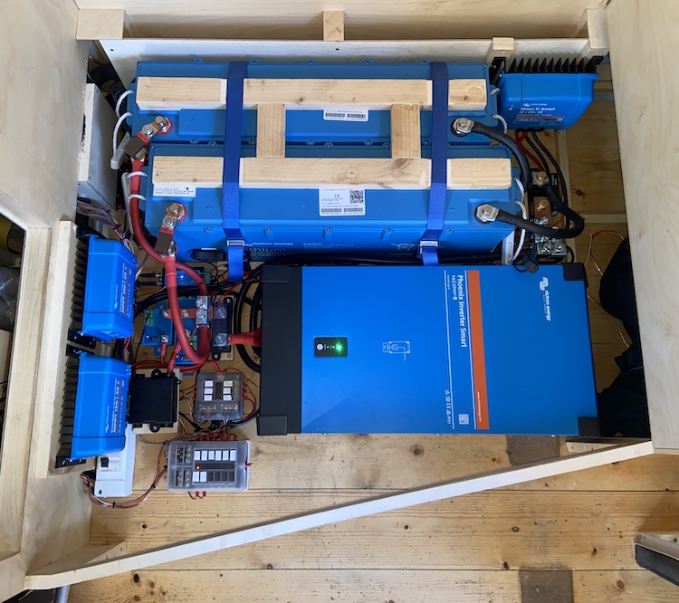
I started questioning my setup. But the interrupted supply chains forced me to stick to the 230V system. The Phoenix inverter of Victron Energy caught my attention. It was equipped with a smart eco-mode feature that would shut down the inverter while idling and regularly provide a voltage of 230V to shortly check if any consumers were active. The duration of the intervals and the power thresholds were configurable and made it possible to operate the inverter with only 2W in idle mode. 48Wh a day seemed very acceptable and much better than 600Wh. I had made great experiences with Victron Energy’s products in my van. I didn’t find any other options, so I ended up accepting the high price and bought a Phoenix inverter. I picked the 24V and 5000W version which provided enough capacity for my domestic consumers and all my power tools.
While I spent a couple of days for looking for a suitable inverter, I was much faster selecting the remaining components of the system like a battery management system for balancing the cells, a battery monitor to measure the voltage, current and capacity of the batteries, a 65A battery protector for the DC consumers, a 100A battery protector for the chargers, a 24V to 12V DC-DC converter, a residual-current device to protect the 230V AC system against circuits, fuse boxes, cables, lugs and so on. I finally had all the components and was ready to wire them up!
Wiring the components
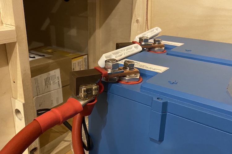
The Phoenix 24/5000 inverter supported a peak power of 10000W, so I had to pick proper cables that would be able to handle about 400A. After reading through the Information Technology Society’s DIN VDE 0298-4 specification that defined current carrying capacities for cables, I decided to use two 95mm² cables to connect the batteries.
I preferred to protect the system against circuits as close to the battery poles as possible. During my research, I found out about CF8 fuses that could be mounted directly on the battery without requiring wires between the battery and the fuse. As I had limited height available, I needed to build a little adapter out of copper that allowed me to mount the fuses in a way that wouldn’t require additional vertical space.
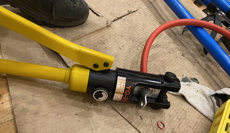
Pressing the lugs on the gigantic cables was quite time consuming and required a big hydraulic press.
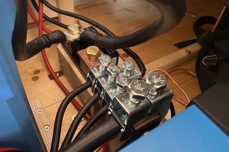
I built a bunch of custom copper bars to reduce the number of cables and lugs.
These copper bars allowed me to efficiently connect the electrical components without needing a lot of space.
During my research, I found solid clamps that were used to connect cables with copper bars in industrial applications.
I saved a lot of time and money using these clamps because I didn’t have to press lugs on all the cables. Compared to the over-priced bus-bars that were advertised on several van, RV and boat shops, the industrial clamps were quite affordable. Most of these expensive bus-bars didn’t even support more than 200A. I struggled finding bus-bars that suited my needs, so I ended up building my own bus-bars using simple copper bars and the clamps. My custom bus-bars were much cheaper and able to handle more than 400A. Connecting the cables was also very pleasant. I liked them a lot!
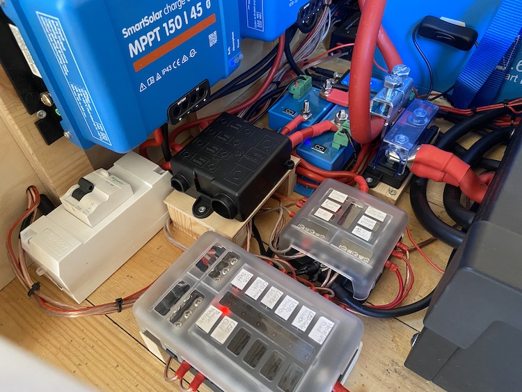
Each consumer and each charger was separately protected by a matching fuse: a 400A MEGA fuse for the inverter, several MIDI fuses for the chargers and blade fuses for the 24V and 12V consumers.
The custom bus-bars helped a lot to fit all components into the limited space between the bathroom and the wardrobe.
Once everything was installed and wired up, I cut, sanded and waxed a thick wooden panel to cover the electrical system.
Testing the system
The system was ready for the first test: I connected a bunch of power tools to the truck’s 230V system: a heat gun, two flood lamps, a table saw and a drill press.
I was finally able to autonomously supply the entire workshop with solar energy. Amazing! :sunny: :electric_plug: