The wood stove that I installed into my Mercedes 508D did a great job keeping the van warm and cosy. However, when spending a few months in Northern Europe, I also noticed a few problems with the heating system in my van: The heat didn’t spread evenly across the cabin. In particular, the lower corners in the back of the van under the seats were usually much colder than the open space around the wood stove. During long lasting wet periods, I had a hard time keeping these corners dry to prevent mold from forming. I also had to go without hot water in the northern hemisphere winter because there wasn’t enough solar energy to run my work laptop and electric boiler, which seemed counterintuitive: hot showers in summer but cold showers in winter?!?
Improving the concept
To overcome the shortcomings of the previous heating system in my van, I developed a new concept for the truck: a hydronic heating system with multiple sources of heat: a wood stove (1), the engine’s cooling system through a separate heat exchanger (2) and an electric boiler (3). With the help of pipes and radiators (5) I would be able to transport the heat into corners and places that were out of reach of the wood stove. Exchanging heat between the cooling circuit of the engine (C1, green) and the heating system of the cabin (C2, purple) would also allow me to preheat the engine with the wood stove on cold days for better starting ability.
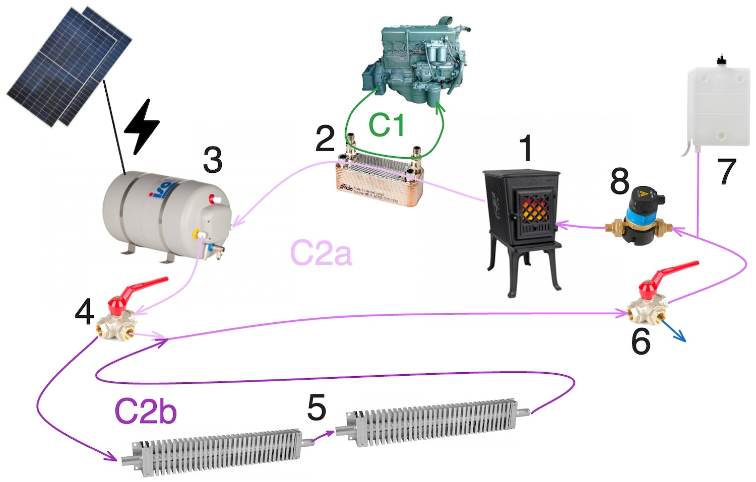
I divided the heating circuit of the cabin into two parts. A short circuit (C2a, bright purple) only connected the heat sources, which would allow me to heat the water in the boiler on warm days without heating the cabin unnecessarily. A three-way valve (4) would allow me to enable an extended circuit (C2b, dark purple), which additionally included a series of radiators placed in all the corners of the cabin to improve the thermal ventilation in these hidden places.
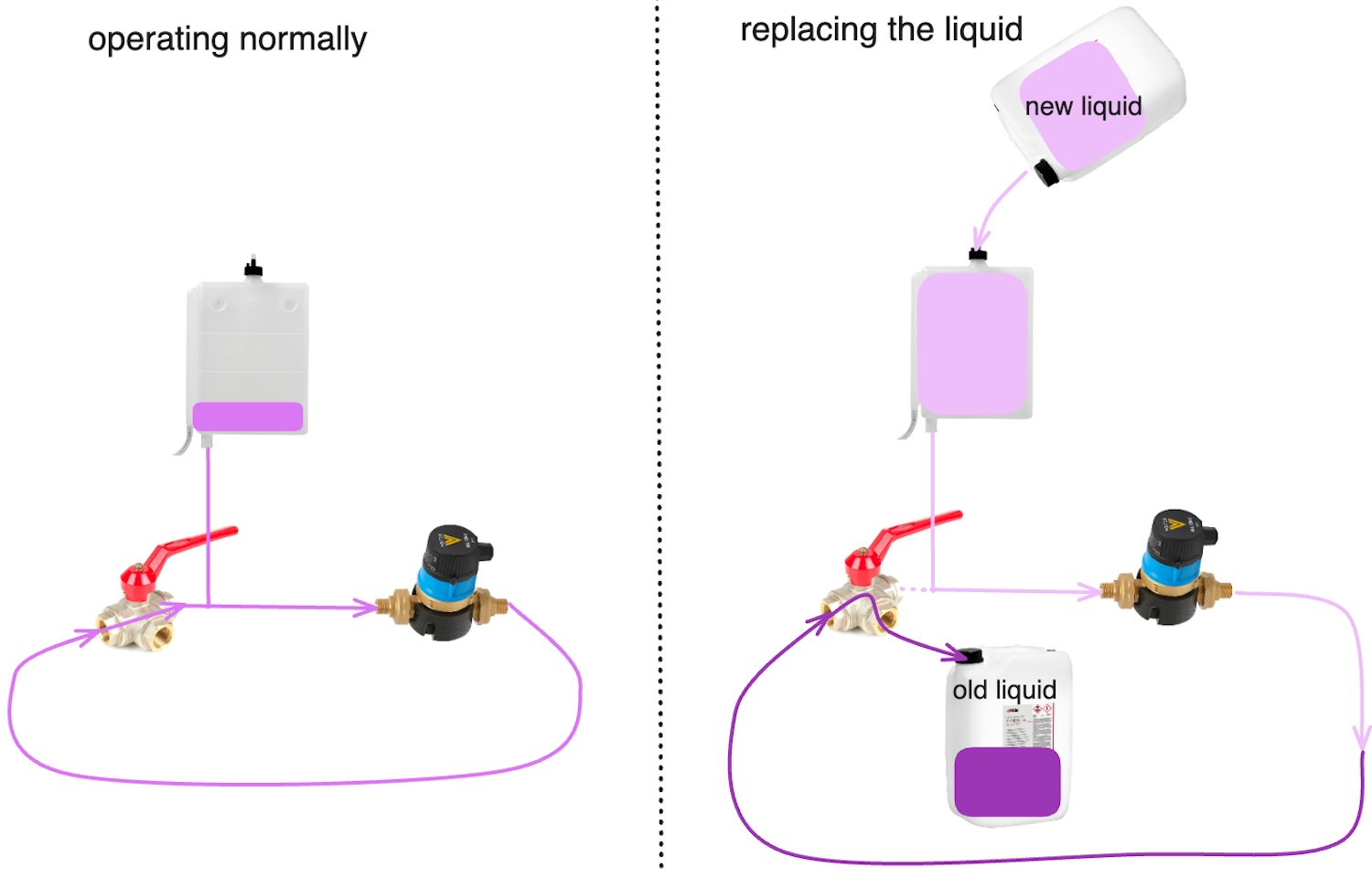
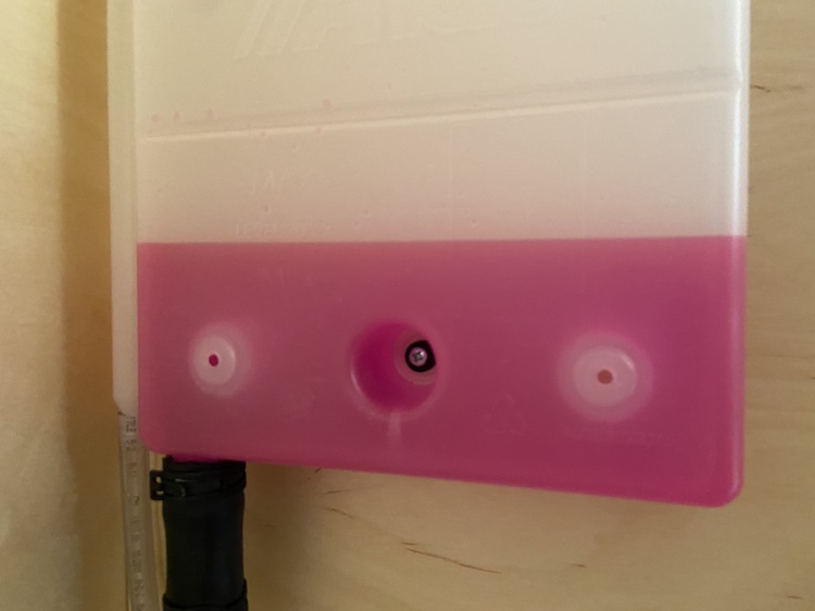
A flexible expansion tank (7) with an air outlet would be mounted at the highest point of the circuit. It was meant to equalize the pressure in the circuit. It also served as inlet for filling the liquid into the heating system. An additional three-way valve (6) mounted before the expansion tank and pump (8) would allow to easily top up, replace or remove the heater liquid:
Using the wood stove as a heat source
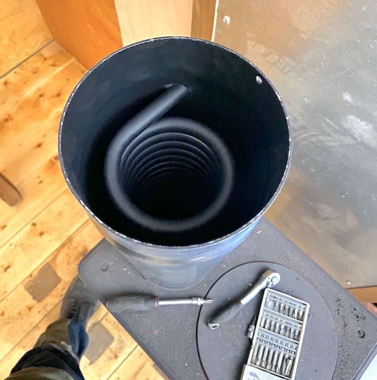
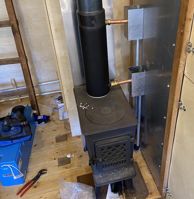
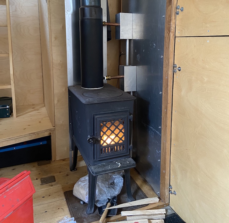
To heat the liquid with the wood stove, I installed a stainless steel coil in the chimney directly above the stove.
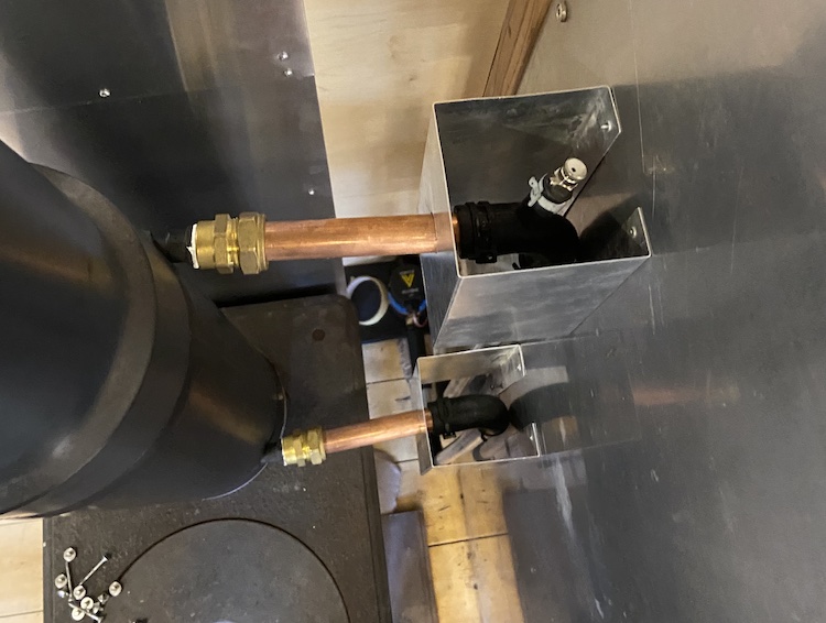
I installed a vent valve behind the outlet of the heat exchanger in the chimney. Since there wasn’t a lot of space between the wall and the chimney, I decided to build aluminum heat shields.
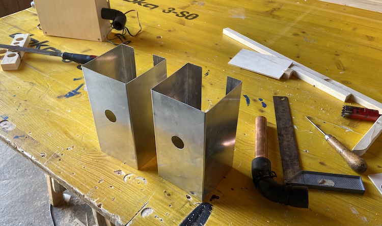
Mounted behind the shields, the rubber angle hoses were protected from the stove’s heat radiation.
By opening the vent valve from the top, air could be easily removed from the heating system.
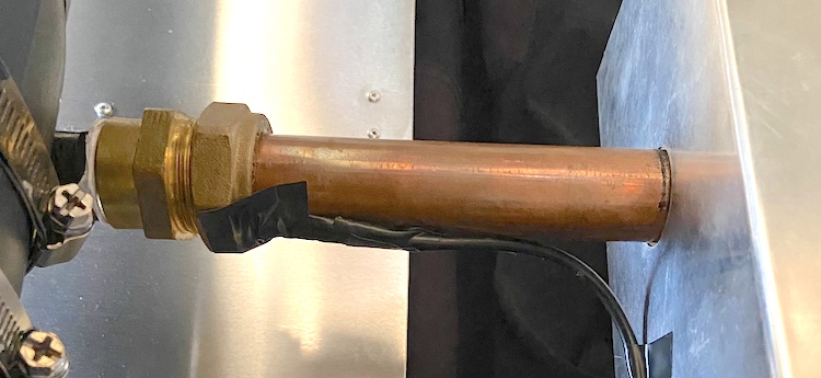
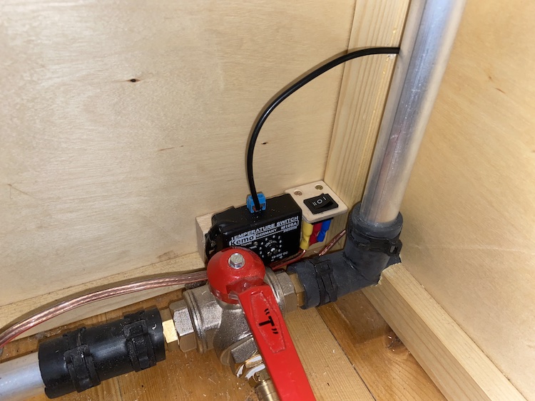
Permanently running the pump seemed like a waste of electricity. The cooling of the smoke while lighting a fire when the chimney was still cold also had a negative effect on the chimney draft, so I attached a heat senor on the outlet of the heat exchanger.
A tiny microcontroller connected to the sensor automatically switched on the pump a few seconds before the liquid in the pipe would begin to boil and switched it off as soon as the pipe would cool down to about 40 to 50 degrees Celsius. Additionally, I installed a switch that would allow to manually override the microcontroller by turning the pump on or off.
Installing the other components
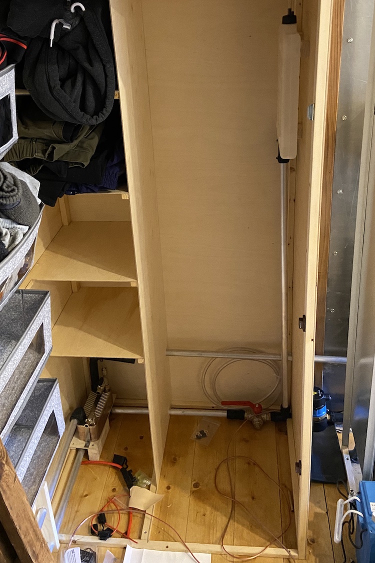
The three-way service valve, expansion tank and heat exchanger for the engine’s cooling system fit nicely into the wardrobe behind the wood stove.
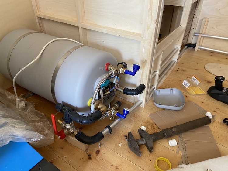
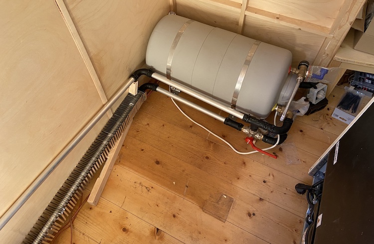
I placed the 25 liter electric boiler right in front of the bathroom to keep the hot water pipes as short a possible.
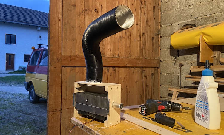
To heat and dry the bathroom, I built a fan supported radiator.
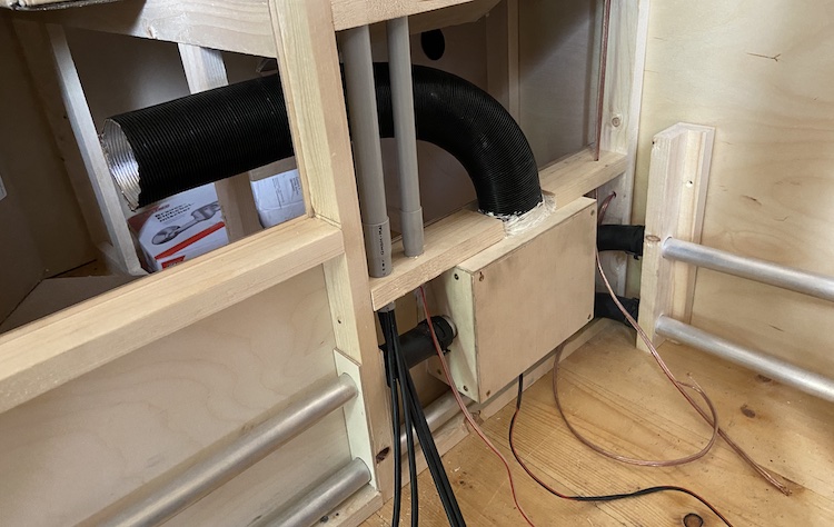
Mounted into the bottom of the cubicle wall, the fans would blow air through the radiator into the bathroom to further increase the radiator’s performance.
Installing the radiators in the living space
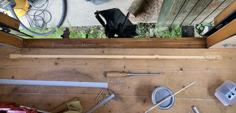
Once the short circuit was installed, I layed the pipes for the extended circuit for heating the living space.
I routed a duct in the floor at the back of the cabin. Embedding the heating pipe directly in front of the back door would have a positive thermal effect on the cold air that might potentially come in through the door gap.
Step by step, I installed all the radiators and vent valves in the places where I planned to build the seating area and install the water tank.
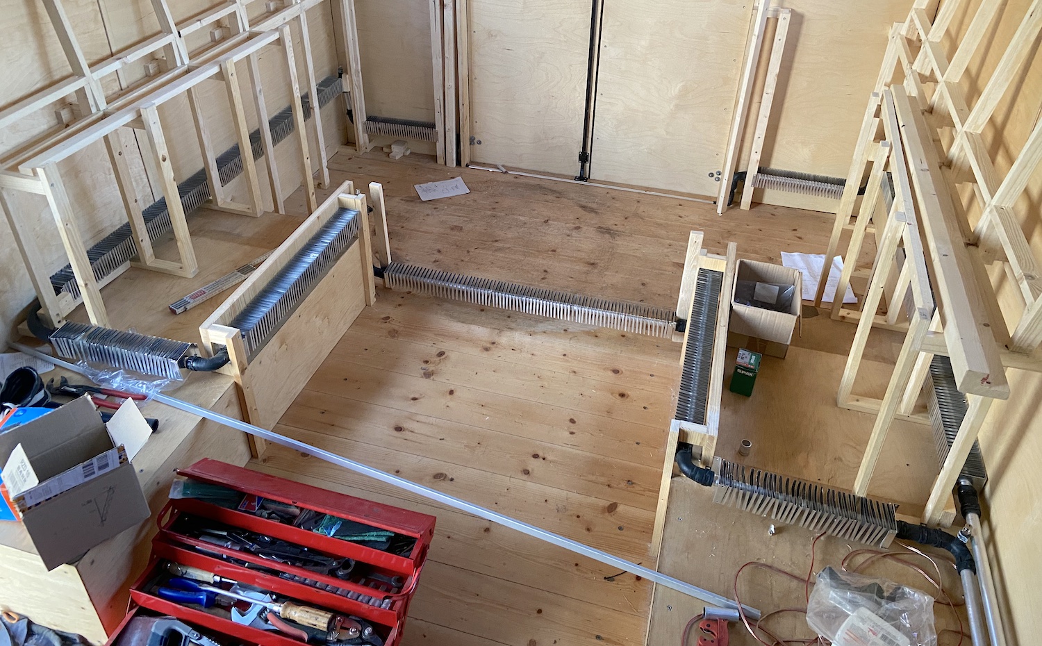
Once all pipes were layed, I could finally fill the liquid (glycol) into the system.
After running the pump for a couple of hours and releasing all the air through the vent valves, the system was ready for its first test!
Shortly after lighting the fire, the pump began pumping fluid through the system. The feeling of warmth in the radiators brought a big smile to my face. I was really happy to have turned my new concept into reality! ![]()
![]()